Operation
Pre-Start
Fill fuel tank on level ground. For best results use only clean, fresh regular grade unleaded gasoline with an octane rating of 87 or higher.
Important: Never use methanol, gasoline containing methanol, gasohol containing more than 10% ethanol, premium gasoline, or white gas because the fuel system could be damaged.
Do Not add oil to gasoline.
Do Not overfill fuel tank. Fill the fuel tank to the bottom of the filler neck. The empty space in the tank allows gasoline to expand. Overfilling may result in fuel leakage or damage to the engine or emission system (if equipped).
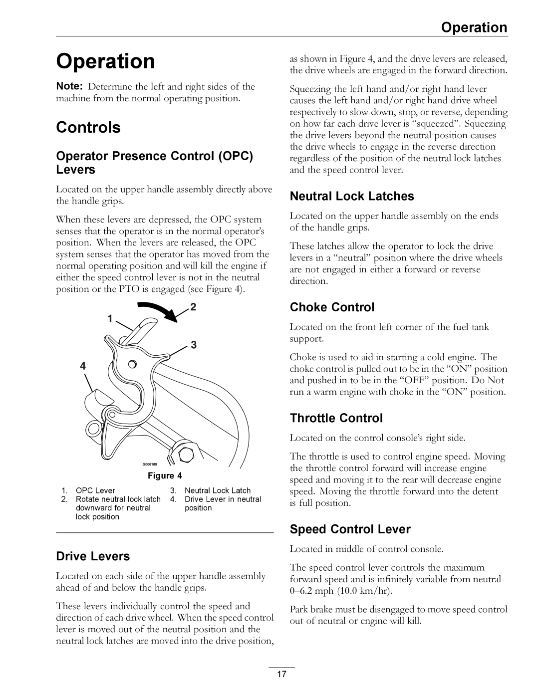
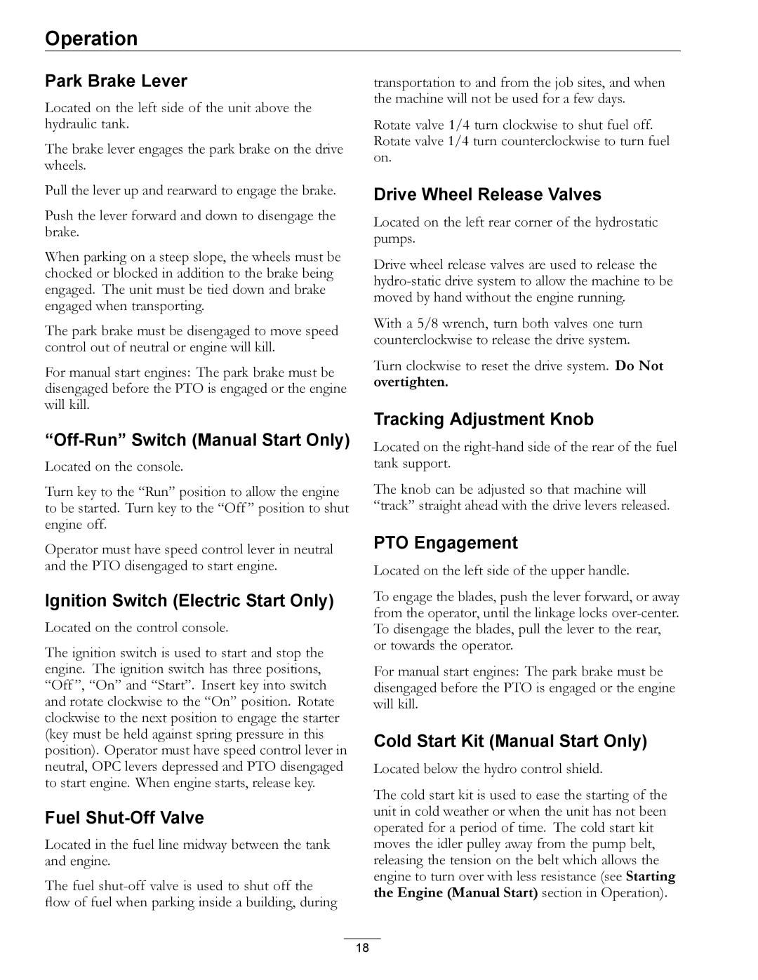
Make sure you understand the controls, their locations, their functions, and their safety requirements.
Refer to the Maintenance section and perform all the necessary inspection and maintenance steps.
Note: After starting the engine and engaging the hydro drive, if either of the drive wheels acts sluggish or will not rotate at all, stop engine and refer to the Hydraulic System Air Purge Procedure in Maintenance.
Operating Instructions
Open the Fuel Shut-Off Valve
Rotate the valve 1/4 turn counterclockwise to turn fuel on.
Starting the Engine (Manual Start)
Note: Operator must have PTO disengaged and speed control lever in neutral position when starting the engine.
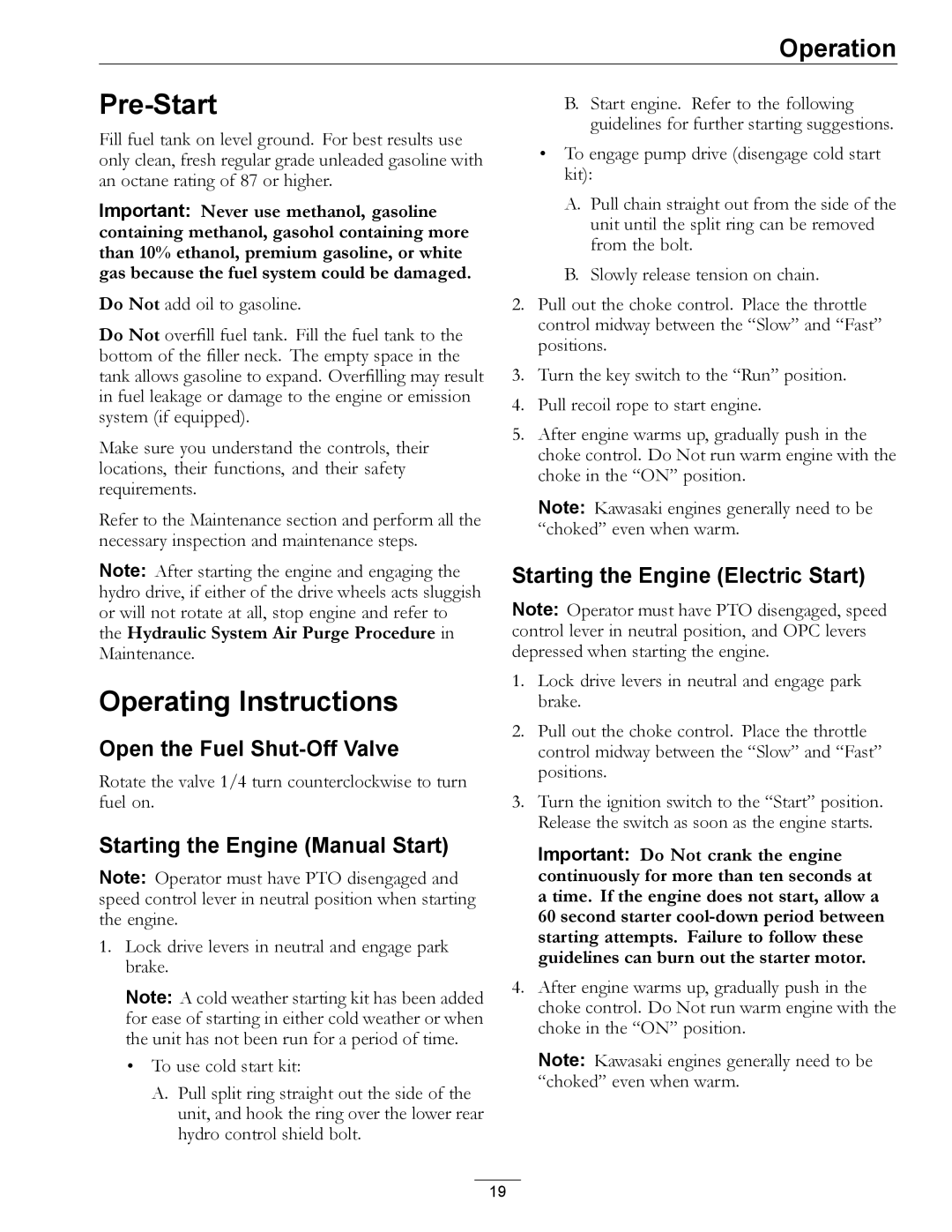
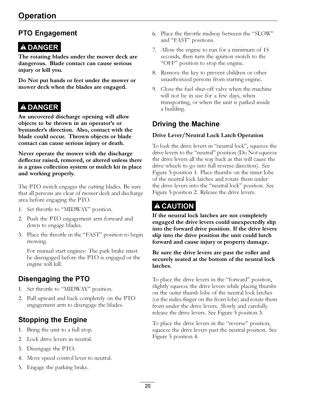
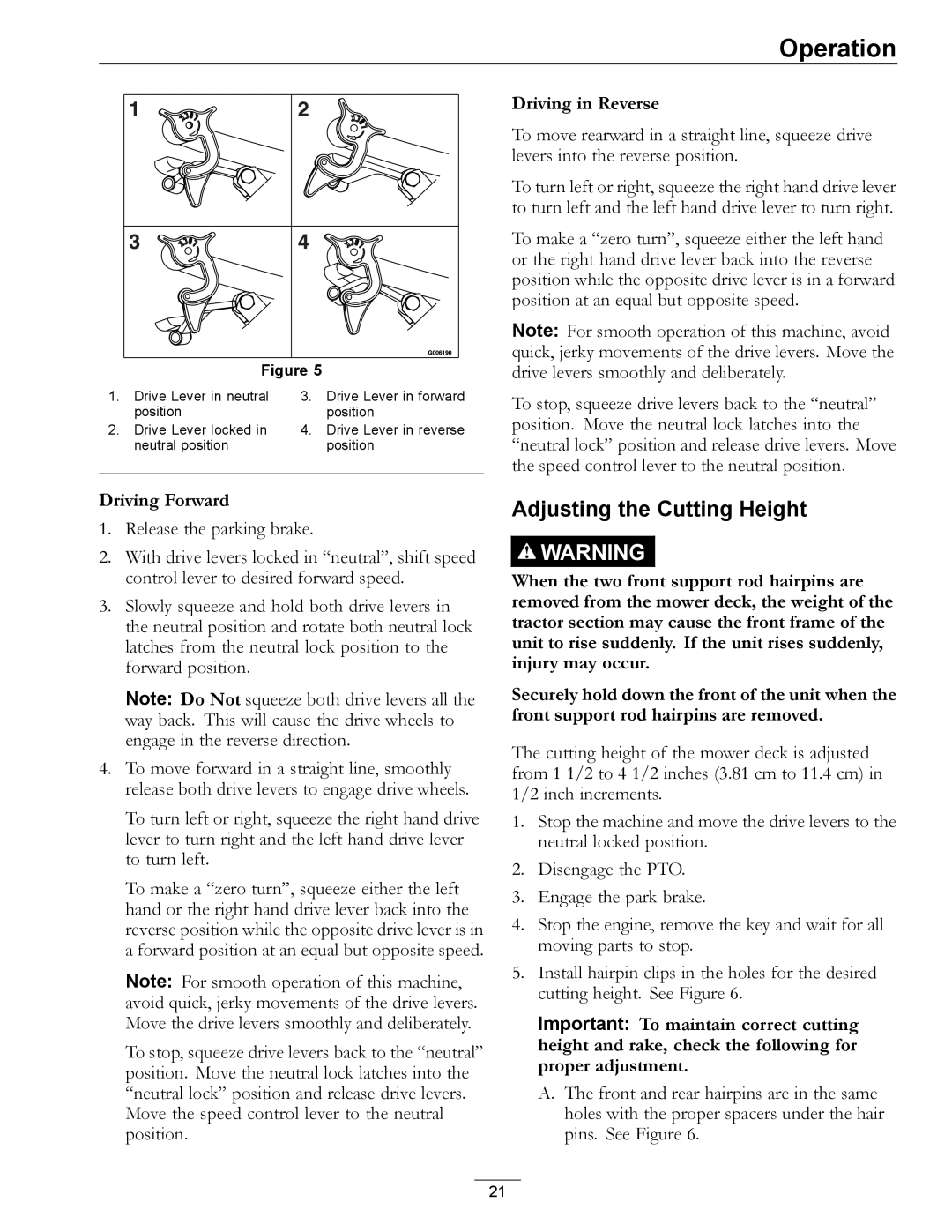
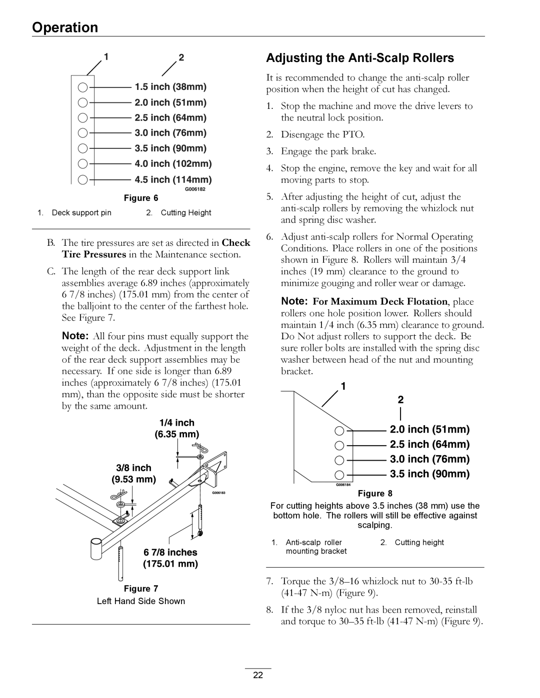
1.Lock drive levers in neutral and engage park brake.
Note: A cold weather starting kit has been added for ease of starting in either cold weather or when the unit has not been run for a period of time.
•To use cold start kit:
A.Pull split ring straight out the side of the unit, and hook the ring over the lower rear hydro control shield bolt.
B.Start engine. Refer to the following guidelines for further starting suggestions.
•To engage pump drive (disengage cold start kit):
A.Pull chain straight out from the side of the unit until the split ring can be removed from the bolt.
B.Slowly release tension on chain.
2.Pull out the choke control. Place the throttle control midway between the “Slow” and “Fast” positions.
3.Turn the key switch to the “Run” position.
4.Pull recoil rope to start engine.
5.After engine warms up, gradually push in the choke control. Do Not run warm engine with the choke in the “ON” position.
Note: Kawasaki engines generally need to be “choked” even when warm.
Starting the Engine (Electric Start)
Note: Operator must have PTO disengaged, speed control lever in neutral position, and OPC levers depressed when starting the engine.
1.Lock drive levers in neutral and engage park brake.
2.Pull out the choke control. Place the throttle control midway between the “Slow” and “Fast” positions.
3.Turn the ignition switch to the “Start” position. Release the switch as soon as the engine starts.
Important: Do Not crank the engine continuously for more than ten seconds at a time. If the engine does not start, allow a 60 second starter
4.After engine warms up, gradually push in the choke control. Do Not run warm engine with the choke in the “ON” position.
Note: Kawasaki engines generally need to be “choked” even when warm.
19
