Quick Installation Guide | 7 |
Power-up Diagnostics
The system runs diagnostic software at power up. This software verifies that every component in the system is operating correctly.
If any component fails during
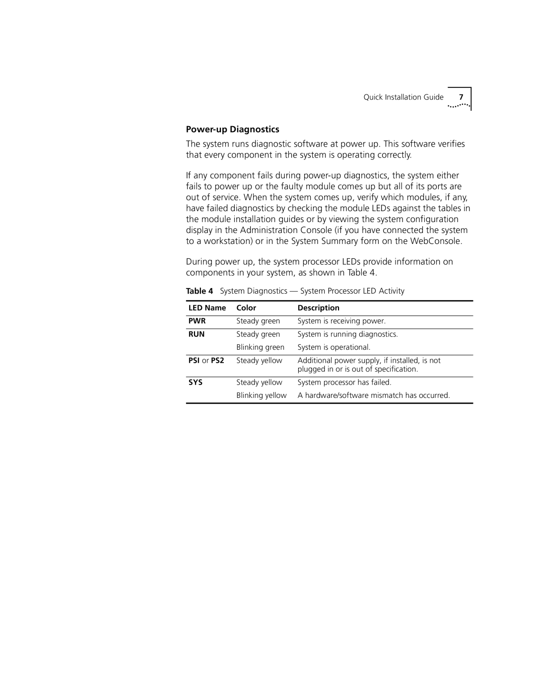
During power up, the system processor LEDs provide information on components in your system, as shown in Table 4.
Table 4 System Diagnostics — System Processor LED Activity
LED Name | Color | Description |
|
|
|
PWR | Steady green | System is receiving power. |
|
|
|
RUN | Steady green | System is running diagnostics. |
| Blinking green | System is operational. |
|
|
|
PSI or PS2 | Steady yellow | Additional power supply, if installed, is not |
|
| plugged in or is out of specification. |
|
|
|
SYS | Steady yellow | System processor has failed. |
| Blinking yellow | A hardware/software mismatch has occurred. |
|
|
|
