Uplink VLAN Configuration Example
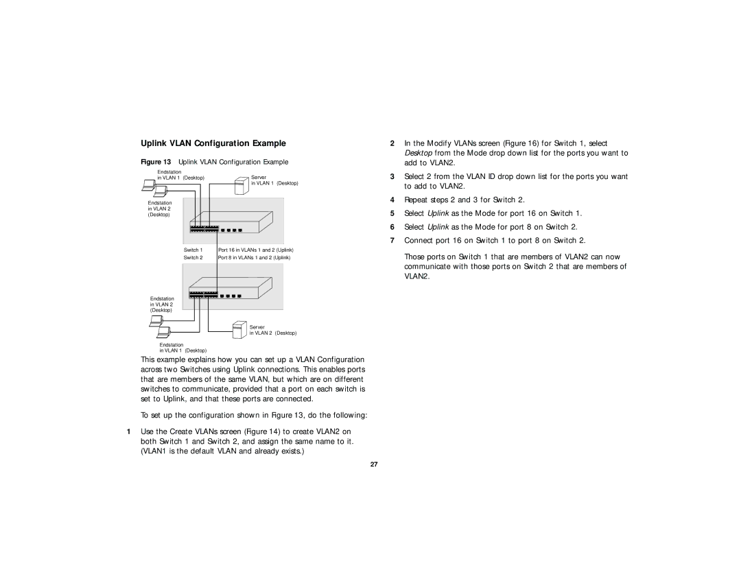
Figure 13 Uplink VLAN Configuration Example | |
Endstation | Server |
in VLAN 1 (Desktop) | |
| in VLAN 1 (Desktop) |
Endstation |
|
in VLAN 2 |
|
(Desktop) |
|
Switch 1 | Port 16 in VLANs 1 and 2 (Uplink) |
Switch 2 | Port 8 in VLANs 1 and 2 (Uplink) |
Endstation |
|
in VLAN 2 |
|
(Desktop) |
|
Server
in VLAN 2 (Desktop)
Endstation
in VLAN 1 (Desktop)
This example explains how you can set up a VLAN Configuration across two Switches using Uplink connections. This enables ports that are members of the same VLAN, but which are on different switches to communicate, provided that a port on each switch is set to Uplink, and that these ports are connected.
To set up the configuration shown in Figure 13, do the following:
1Use the Create VLANs screen (Figure 14) to create VLAN2 on both Switch 1 and Switch 2, and assign the same name to it. (VLAN1 is the default VLAN and already exists.)
2In the Modify VLANs screen (Figure 16) for Switch 1, select Desktop from the Mode drop down list for the ports you want to add to VLAN2.
3Select 2 from the VLAN ID drop down list for the ports you want to add to VLAN2.
4Repeat steps 2 and 3 for Switch 2.
5Select Uplink as the Mode for port 16 on Switch 1.
6Select Uplink as the Mode for port 8 on Switch 2.
7Connect port 16 on Switch 1 to port 8 on Switch 2.
Those ports on Switch 1 that are members of VLAN2 can now communicate with those ports on Switch 2 that are members of VLAN2.
27