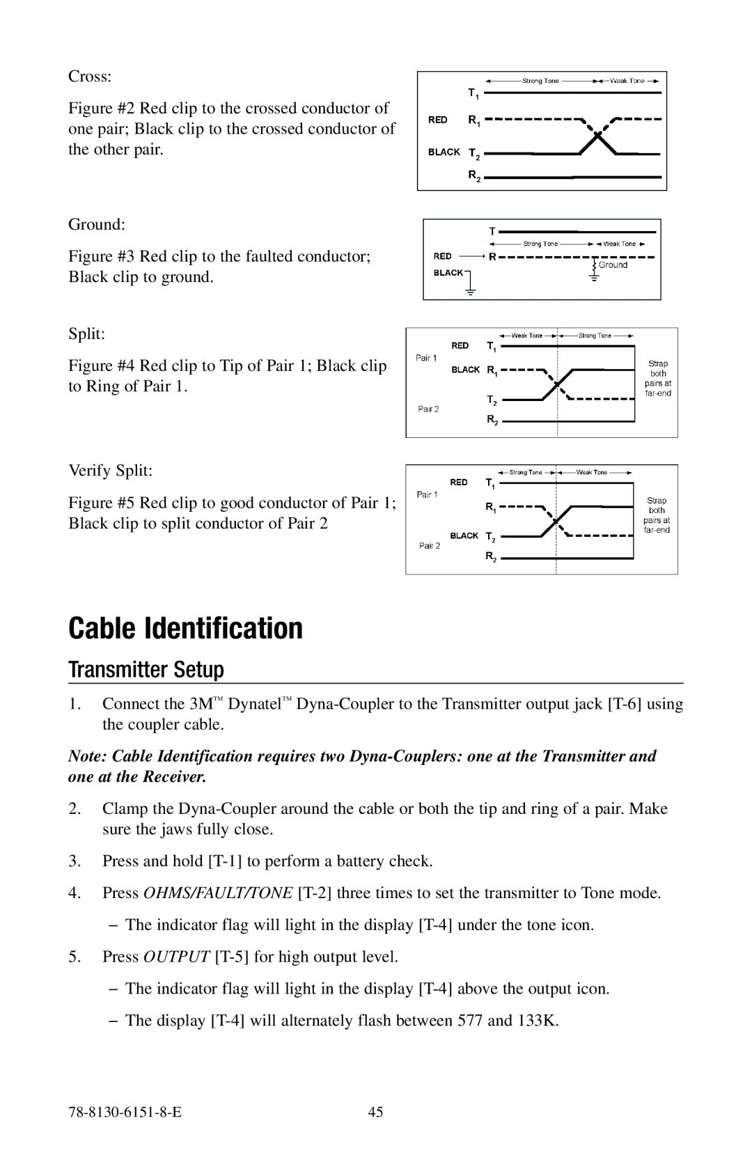
Cross:
Figure #2 Red clip to the crossed conductor of one pair; Black clip to the crossed conductor of the other pair.
Ground:
Figure #3 Red clip to the faulted conductor;
Black clip to ground.
Split:
Figure #4 Red clip to Tip of Pair 1; Black clip to Ring of Pair 1.
Verify Split:
Figure #5 Red clip to good conductor of Pair 1;
Black clip to split conductor of Pair 2
Cable Identification
Transmitter Setup
1.Connect the 3M™ Dynatel™
Note: Cable Identification requires two
2.Clamp the
3.Press and hold
4.Press OHMS/FAULT/TONE
−−The indicator flag will light in the display
5.Press OUTPUT
−−The indicator flag will light in the display
−−The display
| 45 |