11 - SET UP AND ADJUSTMENTS
11.1 Box Width Adjustment
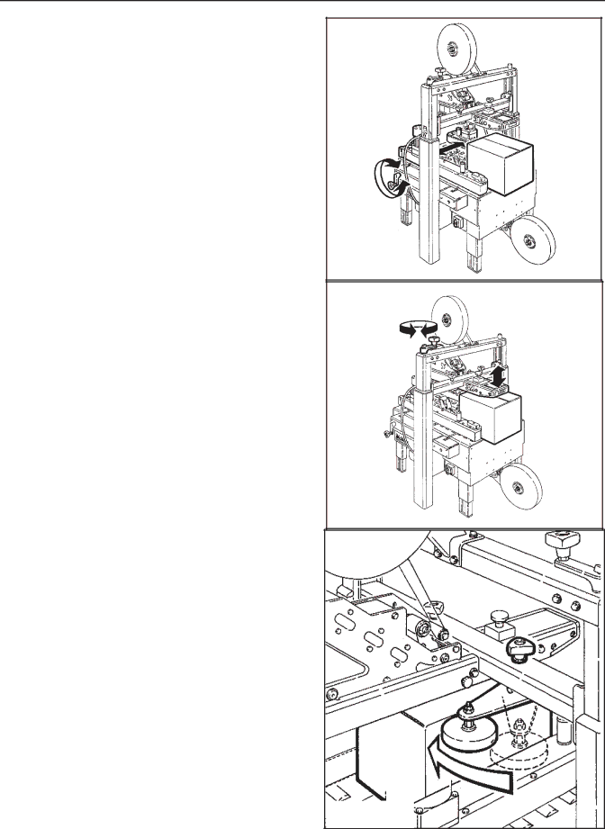
Place a product filled box on infeed end of machine bed with top flaps folded as shown and manually move box forward to contact lower taping head applying roller.
Turn drive belt adjustment crank to position both side drive belts against sides of box (Figure
11.2 Box Height Adjustment
Turn height adjustment crank to position upper taping head onto box. Turn clockwise to lower head, counterclockwise to raise head. Upper taping head must contact and hold top box flaps closed
(Figure
11.3 Adjustment of Top Flap Compression Rollers
The top flap compression rollers have an adjustable slide mounting to provide side compression through the full range of box widths.
Manually move box forward so front of box is aligned with top flap compression rollers.
Adjust the compression rollers against top edge of box and tighten knobs to secure rollers in operating position (Figure
11.4 Changing the Tape Leg Length
Taping heads are preset to apply 70mm [2.75 inches] long tape legs. To change tape leg length to 50mm [2.0 inches], refer to Instructions below and also to Manual 2, "Removing Taping Heads Procedure - Changing the Tape Leg Length".
11.5 Run Boxes to Check Adjustment
Push electrical switch "On" (I) to start drive belts.
Move box forward under upper taping head until it is taken away by drive belts. If box is hard to move under head or is crushed, raise head slightly.
If the box movement is jerky or stops under the upper head, move the side drive belts in slightly to add more pressure between the box and drive belts.
Important – If drive belts are allowed to slip on box, excessive belt wear will occur.
Figure
Figure
Figure
23 | 2011 August |
