Adjustments
WARNING
•To reduce the risk associated with shear, pinch, and entanglement hazards:
-Turn air and electrical supplies off associated equipment before perform- ing any adjustments, maintenance, or servicing the machine or taping heads.
-Never attempt to work on the taping head or load tape while the box drive system is running
Tape Latch Alignment – Figure 5-1
The Latching tape drum assembly is
To move the latch to a position that corresponds to a new tape core width (Figure
1.Remove screw from the latch.
2.Move to the latch to the position that corresponds to the tape core width.
3.Replace screw in the new latch location.
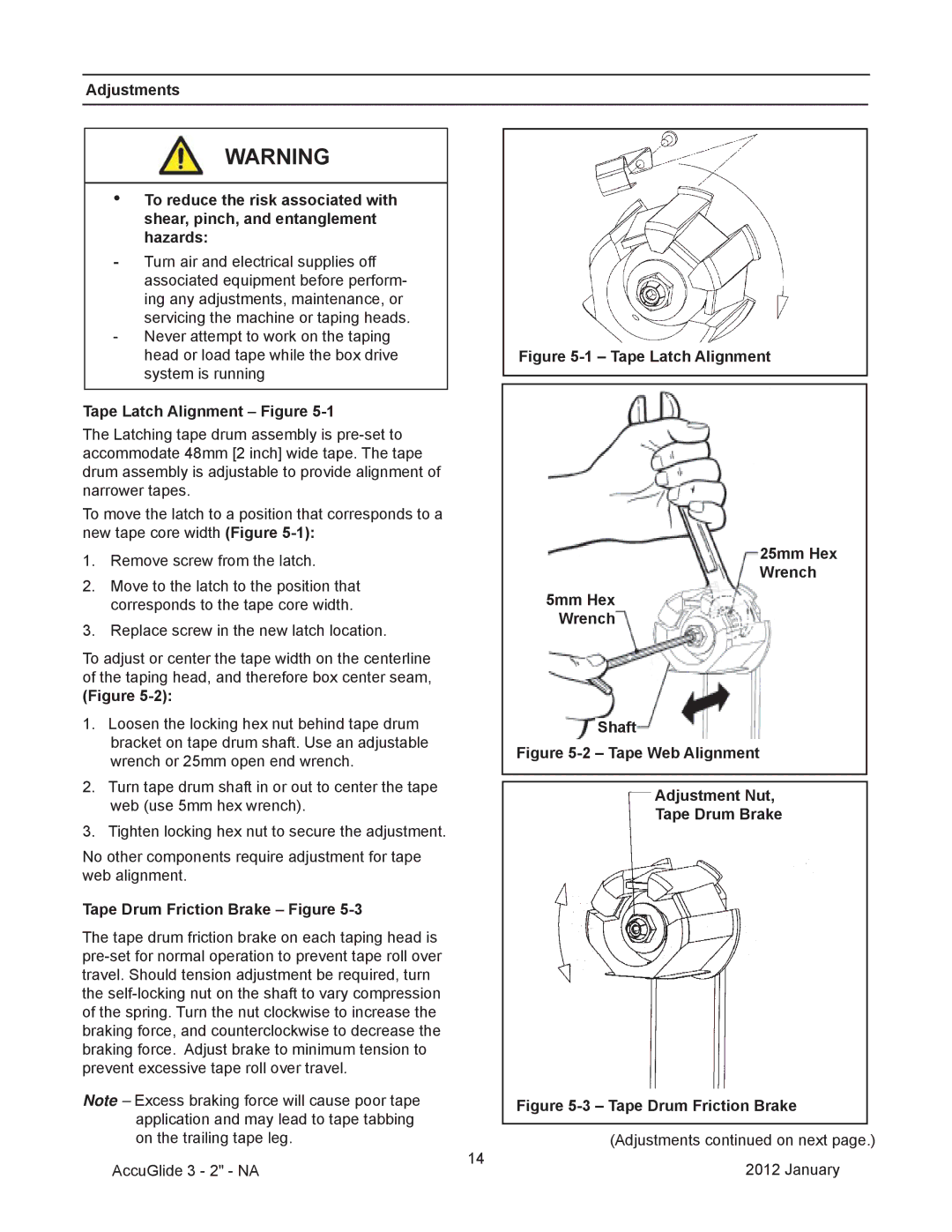
To adjust or center the tape width on the centerline of the taping head, and therefore box center seam,
(Figure
1.Loosen the locking hex nut behind tape drum bracket on tape drum shaft. Use an adjustable wrench or 25mm open end wrench.
2.Turn tape drum shaft in or out to center the tape web (use 5mm hex wrench).
3.Tighten locking hex nut to secure the adjustment.
No other components require adjustment for tape web alignment.
Tape Drum Friction Brake – Figure 5-3
The tape drum friction brake on each taping head is
Note – Excess braking force will cause poor tape application and may lead to tape tabbing on the trailing tape leg.
Figure 5-1 – Tape Latch Alignment
25mm Hex Wrench
5mm Hex Wrench
Shaft
Figure 5-2 – Tape Web Alignment
Adjustment Nut,
Tape Drum Brake
Figure 5-3 – Tape Drum Friction Brake
(Adjustments continued on next page.)
AccuGlide 3 - 2" - NA
14
2012 January