13.11.2 Special
WARNING
•To reduce the risk associated with muscle strain:
−Use the appropriate rigging and material handling equipment when lifting or repositioning this equipment.
−Use proper body mechanics when removing or installing taping heads that are moderately heavy or may be considered awkward to lift.
2.Slide the head forward and lift straight up to remove it from the case sealer.
3.Lift the lower taping head, shown in
Figure 13-8C, straight up to remove it from the case sealer bed.
4.Refer to Manual 2 (Taping Head), See "Adjustments – Changing Tape Leg Length" for taping head set-up.
13.11.3 Drive Belt Assembly Height
The drive belt assemblies can be raised 48mm
[2 inches] to provide better conveying of tall boxes. This change increases the minimum box height that can be taped to 190mm
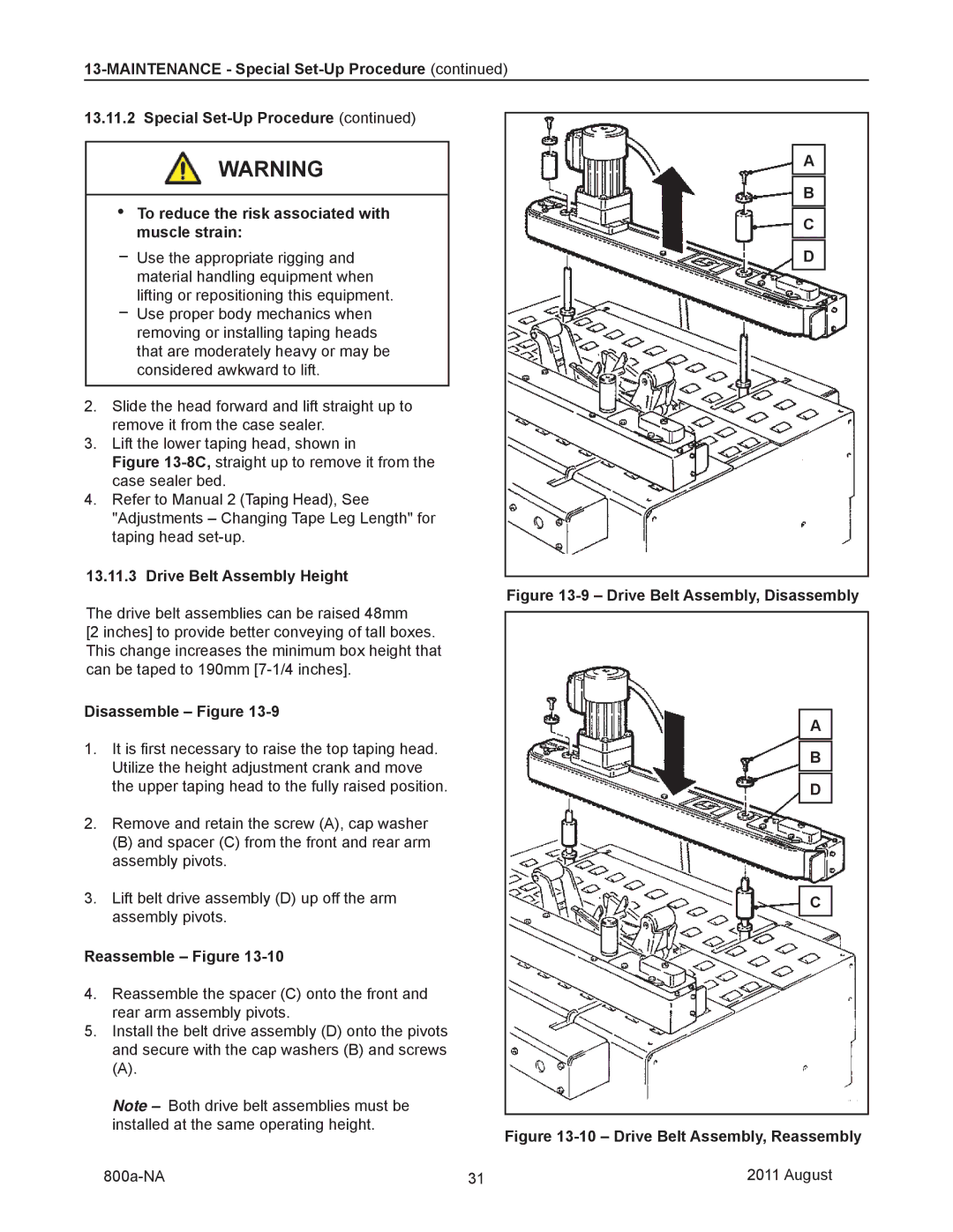
Disassemble – Figure 13-9
1.It is first necessary to raise the top taping head. Utilize the height adjustment crank and move the upper taping head to the fully raised position.
2.Remove and retain the screw (A), cap washer
(B) and spacer (C) from the front and rear arm assembly pivots.
3.Lift belt drive assembly (D) up off the arm assembly pivots.
Reassemble – Figure 13-10
4.Reassemble the spacer (C) onto the front and rear arm assembly pivots.
5.Install the belt drive assembly (D) onto the pivots and secure with the cap washers (B) and screws
(A).
Note – Both drive belt assemblies must be installed at the same operating height.
A
B
C
D
Figure 13-9 – Drive Belt Assembly, Disassembly
A
B
D
C
Figure 13-10 – Drive Belt Assembly, Reassembly
31 | 2011 August |