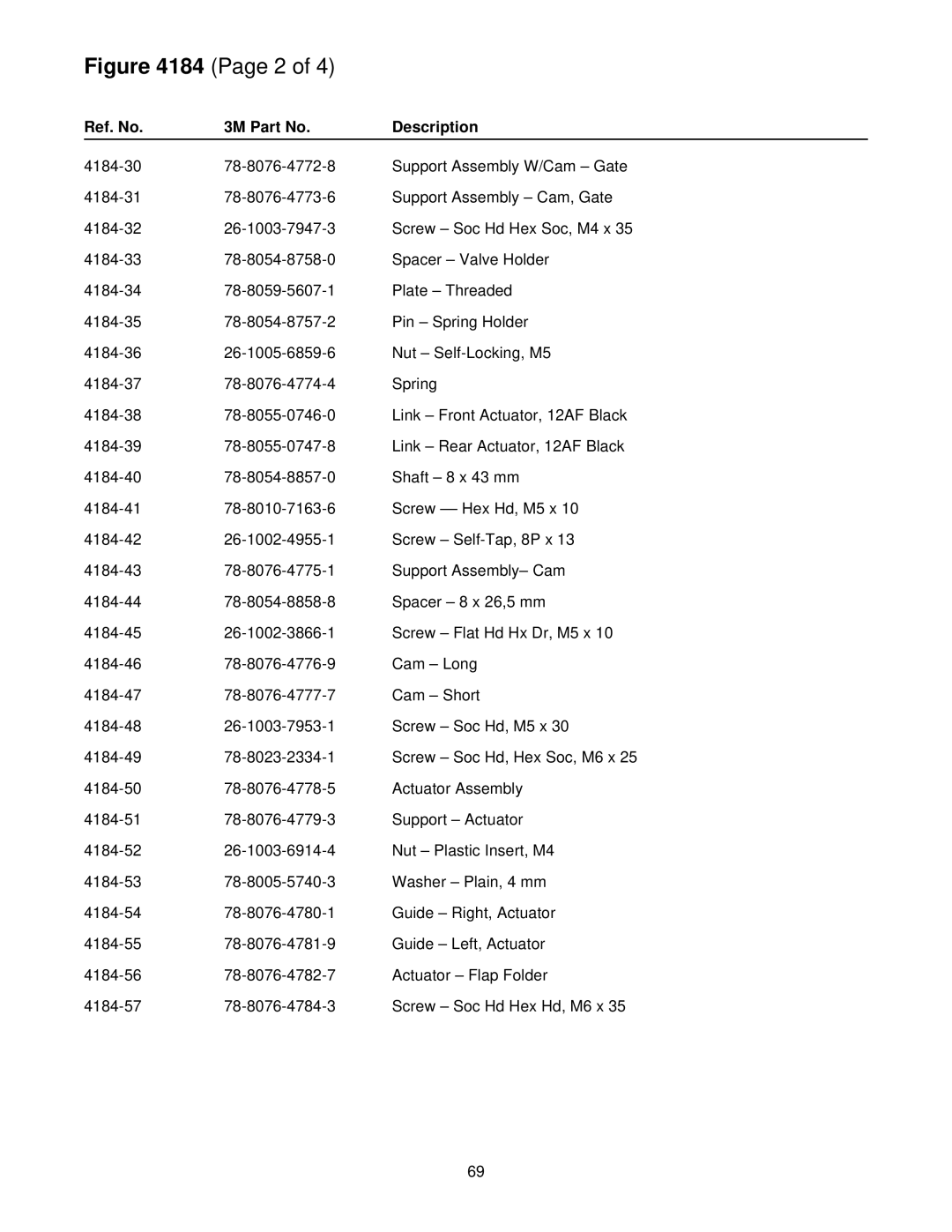
Figure 4184 (Page 2 of 4)
Ref. No. | 3M Part No. | Description |
Support Assembly W/Cam – Gate | ||
Support Assembly – Cam, Gate | ||
Screw – Soc Hd Hex Soc, M4 x 35 | ||
Spacer – Valve Holder | ||
Plate – Threaded | ||
Pin – Spring Holder | ||
Nut – | ||
Spring | ||
Link – Front Actuator, 12AF Black | ||
Link – Rear Actuator, 12AF Black | ||
Shaft – 8 x 43 mm | ||
Screw | ||
Screw – | ||
Support Assembly– Cam | ||
Spacer – 8 x 26,5 mm | ||
Screw – Flat Hd Hx Dr, M5 x 10 | ||
Cam – Long | ||
Cam – Short | ||
Screw – Soc Hd, M5 x 30 | ||
Screw – Soc Hd, Hex Soc, M6 x 25 | ||
Actuator Assembly | ||
Support – Actuator | ||
Nut – Plastic Insert, M4 | ||
Washer – Plain, 4 mm | ||
Guide – Right, Actuator | ||
Guide – Left, Actuator | ||
Actuator – Flap Folder | ||
Screw – Soc Hd Hex Hd, M6 x 35 |
69
