NetVanta 4300/4400 Series | Unit Installation |
|
|
Installing Dial Backup and Network Interface Modules
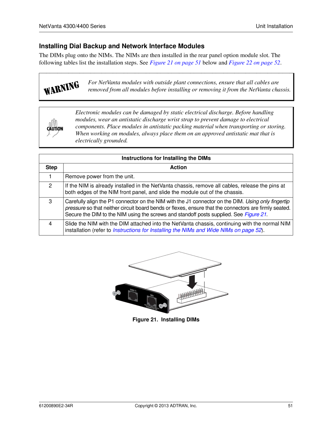
The DIMs plug onto the NIMs. The NIMs are then installed in the rear panel option module slot. The following tables list the installation steps. See Figure 21 on page 51 below and Figure 22 on page 52.
For NetVanta modules with outside plant connections, ensure that all cables are removed from all modules before installing or removing it from the NetVanta chassis.
|
| Electronic modules can be damaged by static electrical discharge. Before handling |
|
| modules, wear an antistatic discharge wrist strap to prevent damage to electrical |
|
| components. Place modules in antistatic packing material when transporting or storing. |
|
| |
|
| When working on modules, always place them on an approved antistatic mat that is |
|
| electrically grounded. |
|
|
|
|
|
|
|
| Instructions for Installing the DIMs |
|
| |
Step | Action | |
1Remove power from the unit.
2If the NIM is already installed in the NetVanta chassis, remove all cables, release the pins at both edges of the NIM front panel, and slide the module out of the chassis.
3Carefully align the P1 connector on the NIM with the J1 connector on the DIM. Using only fingertip pressure so that neither circuit board bends or flexes, ensure that the connectors are firmly seated. Secure the DIM to the NIM using the screws and standoff posts supplied. See Figure 21.
4Slide the NIM with the DIM attached into the NetVanta chassis, continuing with the normal NIM installation (refer to Instructions for Installing the NIMs and Wide NIMs on page 52).
Figure 21. Installing DIMs
Copyright © 2013 ADTRAN, Inc. | 51 |
