APPENDIX A. CONNECTOR PIN DEFINITIONS
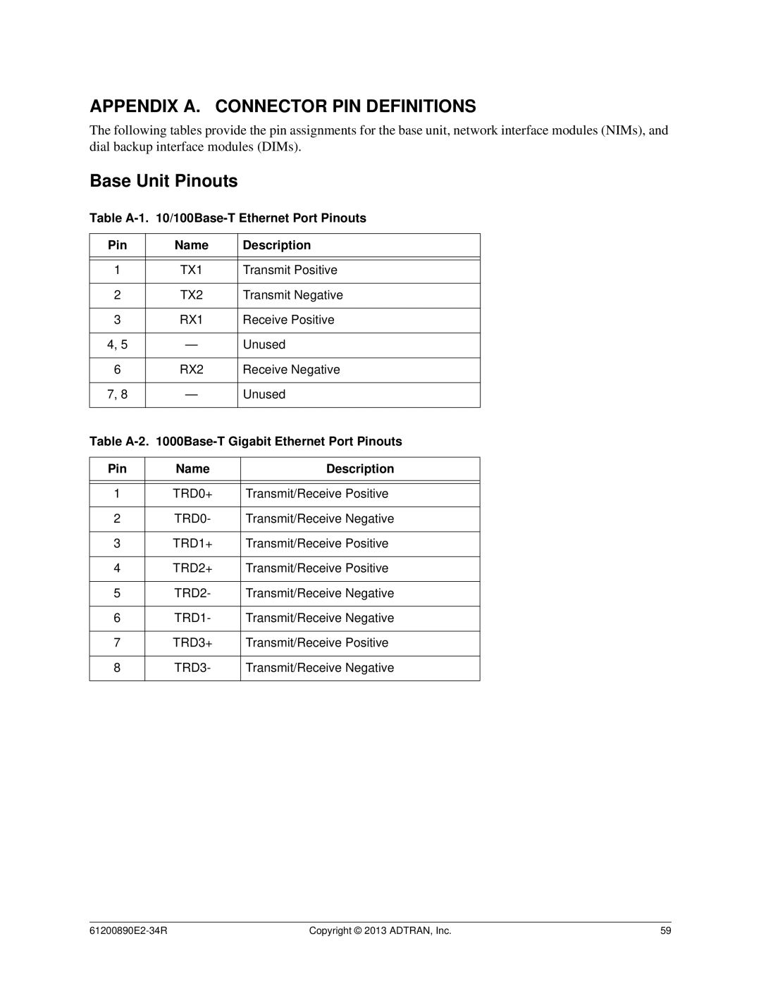
The following tables provide the pin assignments for the base unit, network interface modules (NIMs), and dial backup interface modules (DIMs).
Base Unit Pinouts
Table A-1. 10/100Base-T Ethernet Port Pinouts
Pin | Name | Description |
|
|
|
|
|
|
1 | TX1 | Transmit Positive |
|
|
|
2 | TX2 | Transmit Negative |
|
|
|
3 | RX1 | Receive Positive |
|
|
|
4, 5 | — | Unused |
|
|
|
6 | RX2 | Receive Negative |
|
|
|
7, 8 | — | Unused |
|
|
|
Table
Pin | Name | Description |
|
|
|
|
|
|
1 | TRD0+ | Transmit/Receive Positive |
|
|
|
2 | TRD0- | Transmit/Receive Negative |
|
|
|
3 | TRD1+ | Transmit/Receive Positive |
|
|
|
4 | TRD2+ | Transmit/Receive Positive |
|
|
|
5 | TRD2- | Transmit/Receive Negative |
|
|
|
6 | TRD1- | Transmit/Receive Negative |
|
|
|
7 | TRD3+ | Transmit/Receive Positive |
|
|
|
8 | TRD3- | Transmit/Receive Negative |
|
|
|
Copyright © 2013 ADTRAN, Inc. | 59 |