Physical Descriptions | NetVanta 4300/4400 Series |
|
|
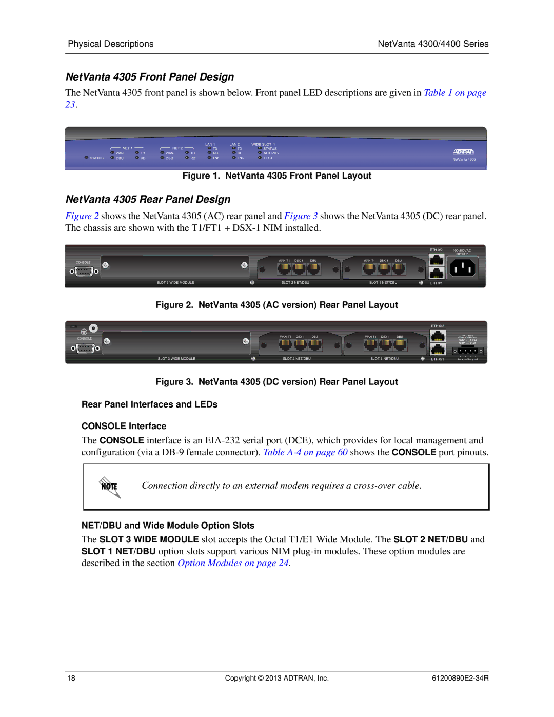
NetVanta 4305 Front Panel Design
The NetVanta 4305 front panel is shown below. Front panel LED descriptions are given in Table 1 on page 23.
| NET 1 |
| NET 2 |
| LAN 1 | LAN 2 | WIDE SLOT 1 |
|
|
|
| TD | TD | STATUS |
| ||
| WAN | TD | WAN | TD | RD | RD | ACTIVITY |
|
STATUS | DBU | RD | DBU | RD | LNK | LNK | TEST | NetVanta 4305 |
Figure 1. NetVanta 4305 Front Panel Layout
NetVanta 4305 Rear Panel Design
Figure 2 shows the NetVanta 4305 (AC) rear panel and Figure 3 shows the NetVanta 4305 (DC) rear panel. The chassis are shown with the T1/FT1 + DSX-1 NIM installed.
|
|
|
|
|
|
| ETH 0/2 | |
|
|
|
|
|
|
|
| 50/60Hz |
CONSOLE | DBU | DBU |
|
| ||||
|
|
|
|
|
|
|
| |
SLOT 3 WIDE MODULE | SLOT 2 NET/DBU |
| SLOT 1 NET/DBU | ETH 0/1 |
| |||
Figure 2. NetVanta 4305 (AC version) Rear Panel Layout
ETH 0/2
CONSOLE | DBU | DBU |
| ||||
|
|
|
|
|
|
| |
SLOT 3 WIDE MODULE | SLOT 2 NET/DBU |
| SLOT 1 NET/DBU | ETH 0/1 | |||
Figure 3. NetVanta 4305 (DC version) Rear Panel Layout
Rear Panel Interfaces and LEDs
CONSOLE Interface
The CONSOLE interface is an
Connection directly to an external modem requires a
NET/DBU and Wide Module Option Slots
The SLOT 3 WIDE MODULE slot accepts the Octal T1/E1 Wide Module. The SLOT 2 NET/DBU and SLOT 1 NET/DBU option slots support various NIM
18 | Copyright © 2013 ADTRAN, Inc. |