Appendix D. Operation
D.1 Quadrature encoder introduction
In typical
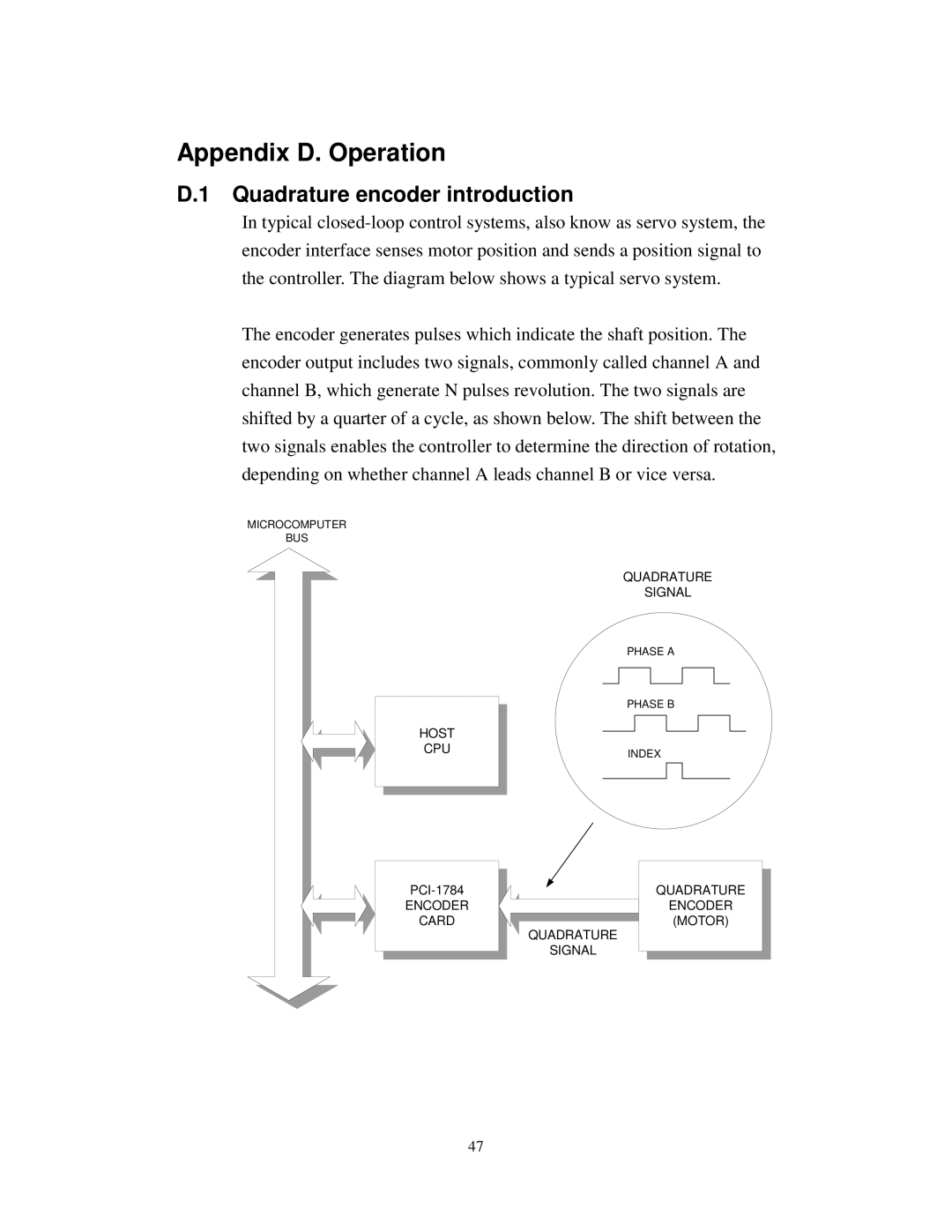
The encoder generates pulses which indicate the shaft position. The encoder output includes two signals, commonly called channel A and channel B, which generate N pulses revolution. The two signals are shifted by a quarter of a cycle, as shown below. The shift between the two signals enables the controller to determine the direction of rotation, depending on whether channel A leads channel B or vice versa.
MICROCOMPUTER
BUS
HOST
CPU
ENCODER
CARD
QUADRATURE
SIGNAL
PHASE A
PHASE B
INDEX
QUADRATURE ENCODER (MOTOR)
QUADRATURE
SIGNAL
47