Single-ended vs. differential input
Most encoders produce square wave signals with TTL levels. Industrial systems often use encoder with differential signals, i.e. channel A and B and their complements. Differential signals can reduce sensitivity to noise and allow longer transmission distances. Encoders may also produce a third signal once per revolution know as the index or marker. The encoder interface can use the index signal to reset the counter, allowing you to monitor the position within the current revolution.
D.2 Counter modes
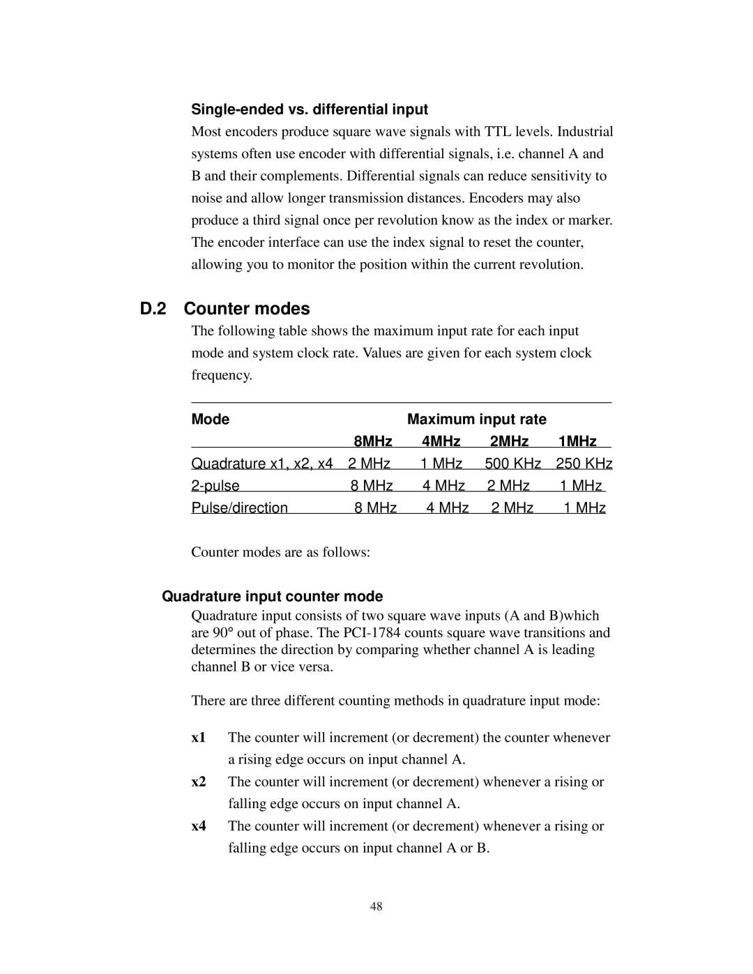
The following table shows the maximum input rate for each input mode and system clock rate. Values are given for each system clock frequency.
Mode |
| Maximum input rate |
|
|
| |
| 8MHz | 4MHz | 2MHz | 1MHz |
| |
Quadrature x1, x2, x4 | 2 MHz | 1 MHz | 500 KHz | 250 KHz | ||
8 MHz | 4 MHz | 2 MHz | 1 MHz |
| ||
Pulse/direction | 8 MHz | 4 MHz | 2 MHz | 1 MHz |
| |
Counter modes are as follows:
Quadrature input counter mode
Quadrature input consists of two square wave inputs (A and B)which are 90° out of phase. The
There are three different counting methods in quadrature input mode:
x1 The counter will increment (or decrement) the counter whenever a rising edge occurs on input channel A.
x2 The counter will increment (or decrement) whenever a rising or falling edge occurs on input channel A.
x4 The counter will increment (or decrement) whenever a rising or falling edge occurs on input channel A or B.
48
