Your ePlatform Partner
User’s Manual for Advantech
|
|
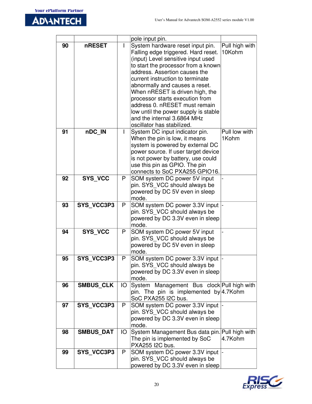
| pole input pin. |
| |
90 | nRESET | I | System hardware reset input pin. | Pull high with | |
|
|
| Falling edge triggered. Hard reset. | 10Kohm | |
|
|
| (input) Level sensitive input used |
| |
|
|
| to start the processor from a known |
| |
|
|
| address. Assertion causes the |
| |
|
|
| current instruction to terminate |
| |
|
|
| abnormally and causes a reset. |
| |
|
|
| When nRESET is driven high, the |
| |
|
|
| processor starts execution from |
| |
|
|
| address 0. nRESET must remain |
| |
|
|
| low until the power supply is stable |
| |
|
|
| and the internal 3.6864 MHz |
| |
|
|
| oscillator has stabilized. |
| |
91 | nDC_IN | I | System DC input indicator pin. | Pull low with | |
|
|
| When the pin is low, it means | 1Kohm | |
|
|
| system is powered by external DC |
| |
|
|
| power source. If user target device |
| |
|
|
| is not power by battery, use could |
| |
|
|
| use this pin as GPIO. The pin |
| |
|
|
| connects to SoC PXA255 GPIO16. |
| |
92 | SYS_VCC | P | SOM system DC power 5V input | - | |
|
|
| pin. SYS_VCC should always be |
| |
|
|
| powered by DC 5V even in sleep |
| |
|
|
| mode. |
|
|
93 | SYS_VCC3P3 | P | SOM system DC power 3.3V input | - | |
|
|
| pin. SYS_VCC should always be |
| |
|
|
| powered by DC 3.3V even in sleep |
| |
|
|
| mode. |
|
|
94 | SYS_VCC | P | SOM system DC power 5V input | - | |
|
|
| pin. SYS_VCC should always be |
| |
|
|
| powered by DC 5V even in sleep |
| |
|
|
| mode. |
|
|
95 | SYS_VCC3P3 | P | SOM system DC power 3.3V input | - | |
|
|
| pin. SYS_VCC should always be |
| |
|
|
| powered by DC 3.3V even in sleep |
| |
|
|
| mode. |
|
|
96 | SMBUS_CLK | IO | System | Management Bus clock | Pull high with |
|
|
| pin. The | pin is implemented by | 4.7Kohm |
|
|
| SoC PXA255 I2C bus. |
| |
97 | SYS_VCC3P3 | P | SOM system DC power 3.3V input | - | |
|
|
| pin. SYS_VCC should always be |
| |
|
|
| powered by DC 3.3V even in sleep |
| |
|
|
| mode. |
|
|
98 | SMBUS_DAT | IO | System Management Bus data pin. | Pull high with | |
|
|
| The pin is implemented by SoC | 4.7Kohm | |
|
|
| PXA255 I2C bus. |
| |
99 | SYS_VCC3P3 | P | SOM system DC power 3.3V input | - | |
|
|
| pin. SYS_VCC should always be |
| |
|
|
| powered by DC 3.3V even in sleep |
| |
20