Theory of Operation
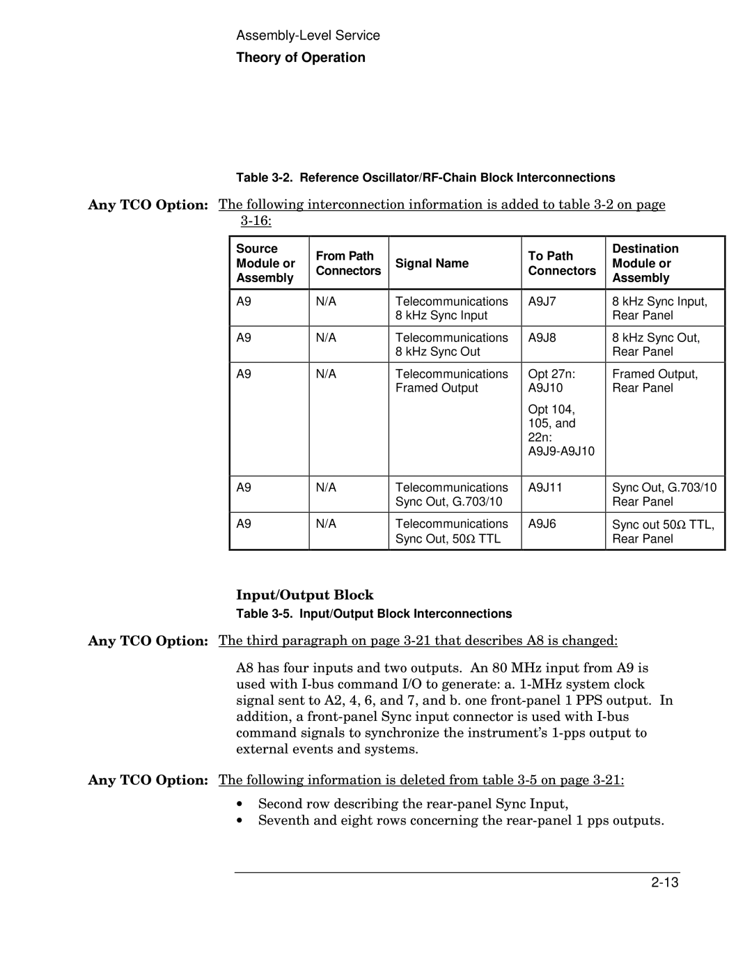
Table 3-2. Reference Oscillator/RF-Chain Block Interconnections
Any TCO Option: The following interconnection information is added to table
Source Module or Assembly
A9
A9
A9
From Path Connectors
N/A
N/A
N/A
Signal Name
Telecommunications 8 kHz Sync Input
Telecommunications 8 kHz Sync Out
Telecommunications Framed Output
To Path Connectors
A9J7
A9J8
Opt 27n:
A9J10
Opt 104, 105, and 22n:
Destination
Module or
Assembly
8 kHz Sync Input, Rear Panel
8 kHz Sync Out, Rear Panel
Framed Output, Rear Panel
A9
A9
N/A
N/A
Telecommunications Sync Out, G.703/10
Telecommunications Sync Out, 50Ω TTL
A9J11
A9J6
Sync Out, G.703/10 Rear Panel
Sync out 50Ω TTL, Rear Panel
Input/Output Block
Table
Any TCO Option: The third paragraph on page
A8 has four inputs and two outputs. An 80 MHz input from A9 is used with
Any TCO Option: The following information is deleted from table
•Second row describing the
•Seventh and eight rows concerning the