Theory of Operation
Option 048: The slot/module interconnect diagram on page
The J3 Low Current Steering Logic connector does not have +5 VDC, POWER FAIL, or BAT VALID signals present.
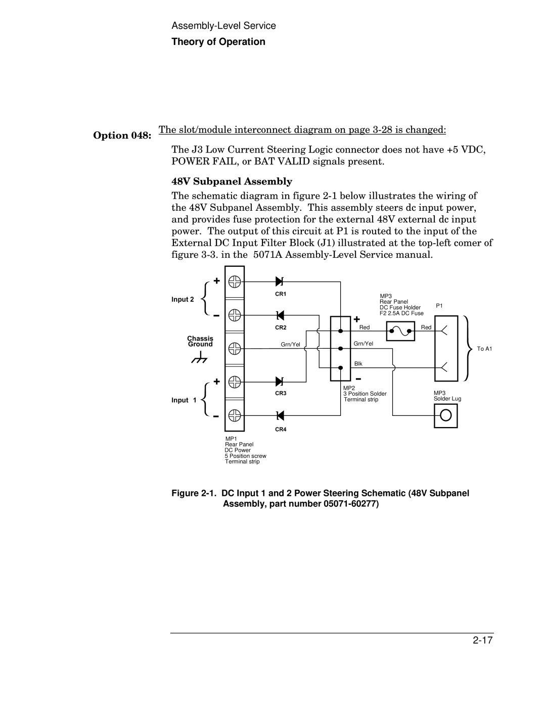
48V Subpanel Assembly
The schematic diagram in figure
+
Input 2
-
Chassis
Ground
+
Input 1
-
CR1 | MP3 |
|
| Rear Panel | P1 |
| DC Fuse Holder | |
| F2 2.5A DC Fuse | |
| + |
|
CR2 | Red | Red |
Grn/Yel | Grn/Yel | To A1 |
|
| |
| Blk |
|
| - |
|
| MP2 | MP3 |
CR3 | 3 Position Solder | |
| Terminal strip | Solder Lug |
CR4
MP1
Rear Panel
DC Power
5 Position screw Terminal strip