Auto-Parallel Programming. Program only the output current of the first ("master") supply in the series; the "slave" supplies automatically track the master's output. Program the output current of the slave supplies to zero. However, the voltage and OVP settings of the slave supplies must be set higher than the operating voltage of the master supply. This ensures that the slave supplies will operate in CC mode. Functions such as status, voltage readback, and current readback can still be read back individually for each supply.

If a "slave" supply experiences a desired shutdown condition (such as overtemperature or overcurrent), it will not automatically shut down all other supplies. You must first enable remote inhibit (RI) and discrete fault indicator (DFI) operation. See "Fault/Inhibit Operation" in Appendix D for wiring information and "Questionable Status Group" in Chapter 4 of the Programming Guide for programming information.

Follow the following operating precautions if you are connecting three of these models in auto-parallel.

You must use caution when connecting three Series 664xA or 665xA power supplies for auto-parallel operation. That is because of the OVP crowbar circuits within these supplies. If the OVP circuit of the second "slave" trips, its crowbar circuit will draw current from the other two supplies. Although some models can withstand this current, the higher-current models in each series (particularly the Agilent 6651A) may be damaged in this situation. Use any of the following operating techniques to avoid possible problems.

1. Program Slave 2 OVP to the Maximum Level

The following technique minimizes the chance that the slave 2 OVP circuit will trip.

a.Program the OVP level of the master and of slave 1 to the desired protection level (below the maximum level specified in Table 1-2).

b.Program the OV protection level of slave 2 to its maximum value.

2.Enable OCP on the Master

You can do this if the combination of all three supplies is being used in the CV mode and the CC mode is only being used as a current limit. Enable OCP on the master supply. If the OVP on either slave trips it will drive the master into CC mode, thereby tripping its OCP. This will shut down all three supplies. This technique will work unless the system is programmed for very low (0.5 to 1.5) output voltages.

3.Insert Protection Diodes

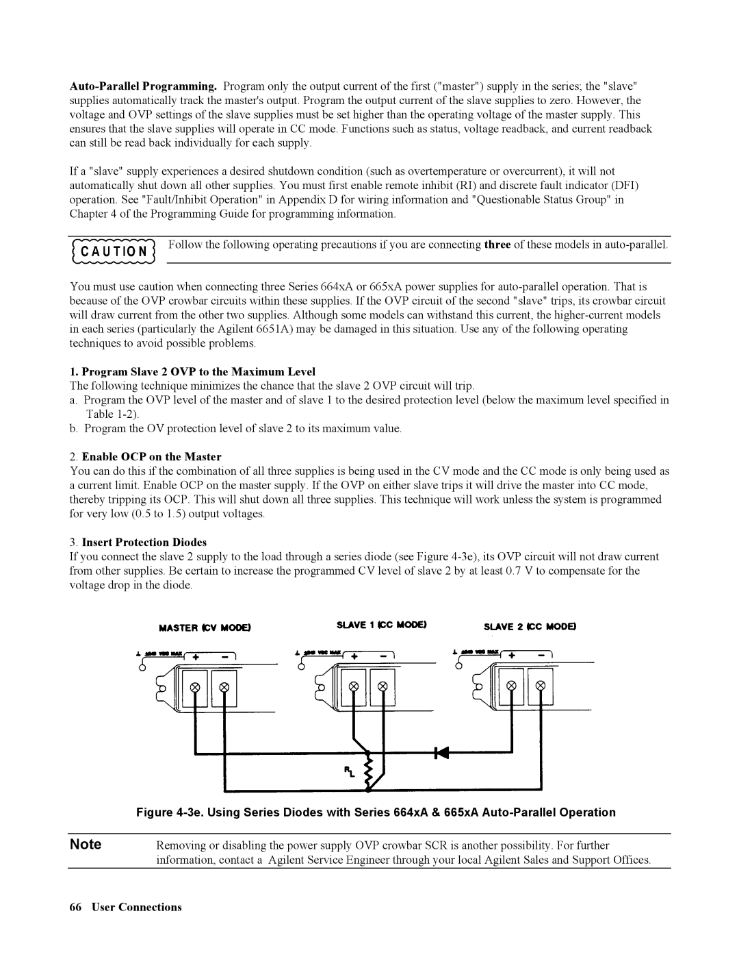
If you connect the slave 2 supply to the load through a series diode (see Figure 4-3e), its OVP circuit will not draw current from other supplies. Be certain to increase the programmed CV level of slave 2 by at least 0.7 V to compensate for the voltage drop in the diode.


Figure 4-3e. Using Series Diodes with Series 664xA & 665xA Auto-Parallel Operation


Note

Removing or disabling the power supply OVP crowbar SCR is another possibility. For further


information, contact a Agilent Service Engineer through your local Agilent Sales and Support Offices.

66 User Connections

Page 66
Image 66
Agilent Technologies 664xA Program Slave 2 OVP to the Maximum Level, Enable OCP on the Master, Insert Protection Diodes

668xA, 669xA, 667xA, 664xA, 665xA specifications

Agilent Technologies has long been a pioneer in the production of high-performance electronic test and measurement instruments, particularly in the field of power sources. Among its notable offerings are the Agilent 667xA, 669xA, 665xA, 664xA, and 668xA series of power supplies. These instruments are designed to provide stable, reliable power for a variety of applications, including electronic testing, industrial processes, and research laboratories.

The Agilent 667xA series is characterized by its programmability and advanced measurement functions. These power supplies support a wide range of output voltages and currents, allowing for flexible configurations that cater to different testing needs. The built-in measurement capabilities enable users to monitor the voltage, current, and power with high precision, which is essential for ensuring optimal performance in electronic applications.

The Agilent 669xA series stands out with its high-power outputs, making it suitable for demanding applications. These power supplies deliver high voltage and current levels, making them ideal for testing high-performance devices, such as power amplifiers and motor drives. Additionally, the 669xA series includes features such as overvoltage protection and complex output sequencing to enhance the safety and reliability of the testing process.

The Agilent 665xA and 664xA series focus on delivering high accuracy and excellent regulation. These models are particularly known for their low noise operation, which is critical for sensitive applications where precision is paramount. The integrated programming capabilities allow users to automate testing sequences, thus improving efficiency in research and development settings.

The 668xA series features advanced digital signal processing that enhances the precision and stability of the output. Users benefit from features like remote sensing and monitoring, allowing feedback adjustments that maintain output accuracy despite cable losses. Furthermore, the 668xA models can integrate seamlessly with various test environments thanks to their LAN, GPIB, and USB connectivity options.

Overall, the Agilent 667xA, 669xA, 665xA, 664xA, and 668xA power supplies provide a comprehensive range of solutions for diverse electronic testing needs. With their advanced features, superb measurement capabilities, and robust performance, these instruments empower engineers and researchers to conduct their work with confidence, precision, and efficiency.