Pin Configurations and Assignments | 3 |
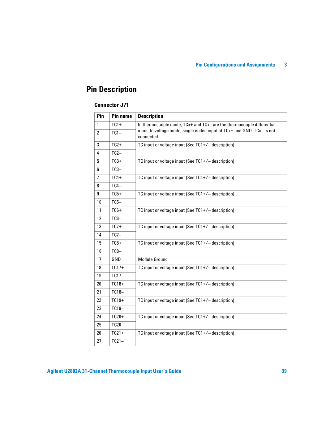
Pin Description
Connector J71
Pin | Pin name | Description | |
|
|
| |
1 | TC1+ | In thermocouple mode, TCx+ and TCx– are the thermocouple differential | |
|
| input. In voltage mode, single ended input at TCx+ and GND. TCx– is not | |
2 | TC1– | ||
connected. | |||
|
| ||
|
|
| |
3 | TC2+ | TC input or voltage input (See TC1+/– description) | |
|
|
| |
4 | TC2– |
| |
|
|
| |
5 | TC3+ | TC input or voltage input (See TC1+/– description) | |
|
|
| |
6 | TC3– |
| |
|
|
| |
7 | TC4+ | TC input or voltage input (See TC1+/– description) | |
|
|
| |
8 | TC4– |
| |
|
|
| |
9 | TC5+ | TC input or voltage input (See TC1+/– description) | |
|
|
| |
10 | TC5– |
| |
|
|
| |
11 | TC6+ | TC input or voltage input (See TC1+/– description) | |
|
|
| |
12 | TC6– |
| |
|
|
| |
13 | TC7+ | TC input or voltage input (See TC1+/– description) | |
|
|
| |
14 | TC7– |
| |
|
|
| |
15 | TC8+ | TC input or voltage input (See TC1+/– description) | |
|
|
| |
16 | TC8– |
| |
|
|
| |
17 | GND | Module Ground | |
|
|
| |
18 | TC17+ | TC input or voltage input (See TC1+/– description) | |
|
|
| |
19 | TC17– |
| |
|
|
| |
20 | TC18+ | TC input or voltage input (See TC1+/– description) | |
|
|
| |
21 | TC18– |
| |
|
|
| |
22 | TC19+ | TC input or voltage input (See TC1+/– description) | |
|
|
| |
23 | TC19– |
| |
|
|
| |
24 | TC20+ | TC input or voltage input (See TC1+/– description) | |
|
|
| |
25 | TC20– |
| |
|
|
| |
26 | TC21+ | TC input or voltage input (See TC1+/– description) | |
|
|
| |
27 | TC21– |
| |
|
|
|
Agilent U2802A | 39 |