Features and Functions | 2 |
Theory of Operation
Functionality of the System
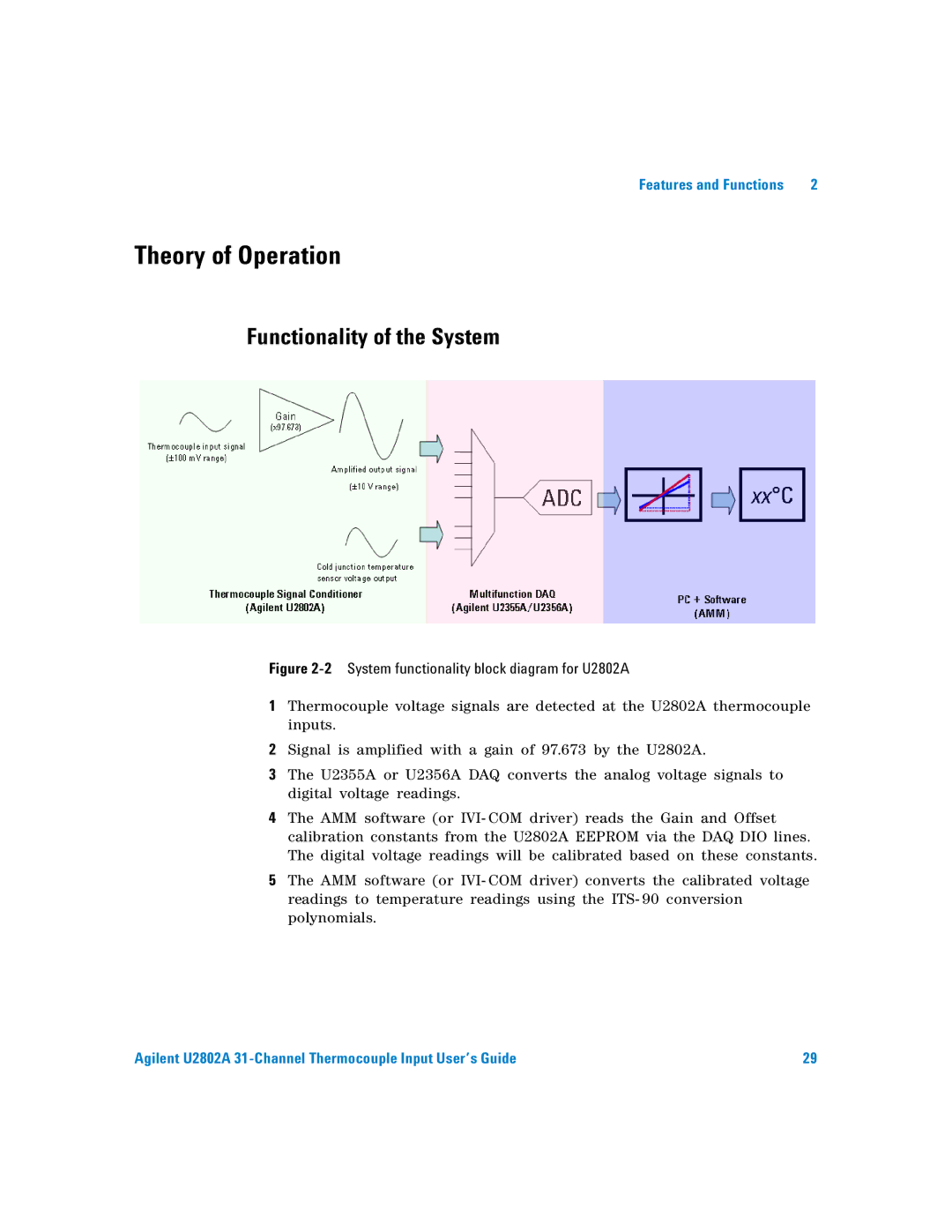
Figure 2-2 System functionality block diagram for U2802A
1Thermocouple voltage signals are detected at the U2802A thermocouple inputs.
2Signal is amplified with a gain of 97.673 by the U2802A.
3The U2355A or U2356A DAQ converts the analog voltage signals to digital voltage readings.
4The AMM software (or IVI- COM driver) reads the Gain and Offset calibration constants from the U2802A EEPROM via the DAQ DIO lines. The digital voltage readings will be calibrated based on these constants.
5The AMM software (or IVI- COM driver) converts the calibrated voltage readings to temperature readings using the ITS- 90 conversion polynomials.
Agilent U2802A | 29 |