Manuals
/
Alamo
/
Lawn and Garden
/
Lawn Mower
Alamo
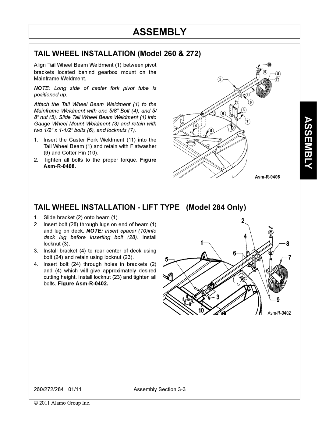
TAIL WHEEL INSTALLATION Model 260, TAIL WHEEL INSTALLATION - LIFT TYPE Model 284 Only
Models:
272
260
284
1
43
136
136
Download
136 pages
39.13 Kb
40
41
42
43
44
45
46
47
Troubleshooting
Specs
Install
Connecting Mower-Lift Type
Warranty
Maintenance
Dealer Setup Instructions
Assembly Section
Engagement Check Procedure
Setting The Mower
Page 43
Image 43
Page 42
Page 44
Page 43
Image 43
Page 42
Page 44
Contents
OPERATOR’S MANUAL
260/272/284
RHINO
ROTARY MOWER
Model Number
To the Owner/Operator/Dealer
Dealer
Telephone
OSHA TRAINING REQUIREMENTS
Alamo Group Ag. Division will provide
one 1 AEM Mower Safety Practices Video
ATTACHMENTS & INSTALLATION
DEALER to CUSTOMER Pre-Delivery/ Operation Instructions
PRE-DELIVERY SERVICE CHECK AND ADJUST OR LUBRICATE AS REQUIRED
SAFETY ITEMS
Page
INTRODUCTION SECTION
Table of Contents
SAFETY SECTION
ASSEMBLY SECTION
MAINTENANCE SECTION
SLIP CLUTCH
BLADE CARRIER INSTALLATION
SEASONAL CLUTCH MAINTENANCE
BLADE REMOVAL
Page
Safety Section
SAFETY SECTION
SAFETY
SAFETY
GENERAL SAFETY INSTRUCTIONS AND PRACTICES
GROUND SPEED WHEN MOWING
OPERATOR SAFETY
GENERAL OPERATING SAFETY
VISIBILITY CONDITIONS WHEN MOWING
ATTACHED
CONNECTION OR DISCONNECTING IMPLEMENT SAFETY
WHEN CONNECTING IMPLEMENT DRIVELINE
DO NOT USE PTO ADAPTER. Using a PTO adapter can cause
TO AVOID CHILDREN FALLING OFF OR BEING CRUSHED BY EQUIPMENT
CRUSHING HAZARDS
WHEN RAISING OR LOWERING IMPLEMENT
WHEN UNHITCHING IMPLEMENT
HIGH GRASS and WEED AREA INSPECTION
THROWN OBJECTS HAZARDS
STOP MOWING IF PASSERSBY ARE WITHIN 300 FEET UNLESS
INSPECT AREA FOR POTENTIAL THROWN OBJECTS BEFORE MOWING
AVOID MOWING in reverse
THROWN OBJECTS HAZARDS CONTINUED
STOP mowing when EXCESSIVE VIBRATION occurs
MOWER OPERATION
WHEN MOUNTING AND DISMOUNTING TRACTOR
RUN OVER HAZARDS
ONLY mount or dismount when tractor and moving parts are stopped
DO NOT USE PTO ADAPTER
PTO ENTANGLEMENT HAZARDS
ROTATING COMPONENTS CONTINUE to ROTATE after the PTO is shut off
PTO SHIELDING
MOWER BLADE CONTACT HAZARDS
HIGH PRESSURE FLUID LEAKS CAN BE INVISIBLE
HIGH PRESSURE OIL LEAK HAZARDS
EQUIP Tractor with a FIRE EXTINGUISHER
ELECTRICAL & FIRE HAZARDS
TRACTOR REQUIREMENTS FOR TOWING OR TRANSPORTING IMPLEMENTS
TRANSPORTING HAZARDS
TOWED MOWERS - ENGAGE TRANSPORT LOCKS AND SAFETY CHAINS
WHEN TOWING OR TRANSPORTING EQUIPMENT
DISCONNECT IMPLEMENT driveline from tractor PTO SHAFT
HAZARDS WITH MAINTENANCE OF IMPLEMENT
BEFORE PERFORMING SERVICE, REPAIRS AND MAINTENANCE ON THE IMPLEMENT
SAFETY SHIELDS, GUARDS AND SAFETY DEVICES INSPECTION
SEE YOUR RHINO DEALER
PARTS INFORMATION
Decal Location
Name 00781327 272 LOGOS Name 00781328 284 LOGOS
Decal Sheets Name 00781352 SAFETY Name 00781326 260 LOGOS
TYPE
DESCRIPTION
Decal Description
SAFETY
SAFETY
SAFETY
SAFETY
SAFETY
SAFETY
SAFETY
SAFETY
SAFETY
DUTIES
Federal Laws and Regulations
Employer-Employee Operator Regulations
This Act Seeks
Introduction Section
INTRODUCTION SECTION
INTRODUCTION
INTRODUCTION
Driveline Size
Equipment Specifications
Gearbox Rating 130HP
130HP
KEY OPERATION POINTS
Warranty information
Operating Noise Level/Sound Pressure
Gibson City, IL
RHINO LIMITED WARRANTY
RHINO
1020 S Sangamon Ave
Page
Assembly Section
ASSEMBLY SECTION
SHIELD ASSEMBLY All Models
ASSEMBLY
ASSEMBLY
DEALER SETUP INSTRUCTIONS
TAIL WHEEL INSTALLATION - LIFT TYPE Model 284 Only
TAIL WHEEL INSTALLATION Model 260
Asm-R-0408
A-FRAME INSTALLATION Quick Hitch Model
DUAL TAIL WHEEL INSTALLATION - LIFT TYPE Model 284 Only
DRIVELINE ATTACHMENT
A-FRAME INSTALLATION Model
TONGUE Pull Type
AXLE ASSEMBLY
WHEELS Model 284 Only
HYDRAULIC OR MANUAL LIFT Model 284 Only
Rear Deflector - Figure Asm-R-0044
Front and Rear Deflectors Standard Equipment
Front Rubber Fabric Deflectors Standard Equipment
Front Deflector Figure Asm-0045
Front Chain Guards Figure Asm-R-0343
CHAIN GUARDS Optional Equipment - All Models
Rear Chain Guard - Figure Asm-R-0344
NOTE Figure ASM-0038 shows optional spring shock installation
CHECK CHAINS Extra Equipment
NOTE 260 and 272 units use a Cat I Kit and 284 Units use a Cat II Kit
OFFSET ADAPTER HITCH EXTRA EQUIPMENT
Page
Operation Section
OPERATION SECTION
OPERATION
OPERATION
RHINO 260/272/284 ROTARY MOWER OPERATION INSTRUCTIONS
PERSONAL PROTECTIVE EQUIPMENT PPE
1. OPERATOR REQUIREMENTS
Tractor Requirements and Capabilities
2. TRACTOR REQUIREMENTS
2.1 ROPS and Seat Belt
2.3 3-Point Hitch
2.2 Tractor Safety Devices
2.6 Power Take Off PTO
2.4 Front End Weight
2.5 Drawbar-Pull Type Mower
3.1 Boarding the Tractor
3. GETTING ON AND OFF THE TRACTOR
Before starting the tractor ensure the following
4. STARTING THE TRACTOR
3.2 Dismounting the Tractor
Essential Tractor Controls
5.1 Connecting Mower-Lift Type
5. CONNECTING THE MOWER TO THE TRACTOR
5.2 3-Point Quick Hitch
5.4 Safety Tow Chain
5.3 Connecting Mower - Lift Type Quick Hitch
6.1 Setting Mower Height- Lift Type - Standard or Quick Hitch
6. SETTING THE MOWER
NOTE Install optional check chains when there is a problem with the hydraulic 3-Point lift maintaining a set height or when a constant pre-adjusted cut height is required. See Check Chains in the Assembly Section for this accessory
6.2 Connecting the Mower-Pull Type
6.3 Setting Mowing Height-Pull Type
Increase Mulching
6.4 Setting Deck Pitch
7. DRIVELINE ATTACHMENT
Lower Horse Power - Better Fuel Efficiency
“Bottoming Out” Check Procedure
7.1 Driveline Length Check
Engagement Check Procedure
8. PRE-OPERATION INSPECTION AND SERVICE
Shorten the driveline profiles as follows
OPERATION
8.2 Mower Pre-Operation Inspection/Service
8.1 Tractor Pre-Operation Inspection/Service
OPERATION
OPERATION
OPERATION
OPS-U-0031
8.3 Cutting Component Inspection
OPERATION
OPERATION
OPERATION
8.4 Blade Bolt Inspection
Make
Tractor PRE-OPERATION Inspection
DO NOT OPERATE an UNSAFE TRACTOR or MOWER
Tractor ID#
Rotary Mower PRE-OPERATION Inspection
9. DRIVING THE TRACTOR AND IMPLEMENT
9.1 Starting the Tractor
9.2 Brake and Differential Lock Setting
9.4 Driving the Tractor and Mower
9.3 Raising the Mower
9.5 Crossing Ditches and Steep Inclines
OPS-R-0022
10. OPERATING THE TRACTOR AND IMPLEMENT
10.1 Foreign Debris Hazards
Raise Mower over solid objects 10.2 Bystanders/Passersby Precautions
Remove Foreign Material
STOP MOWING IF PASSERSBY ARE WITHIN 300 Feet UNLESS
10.3 Engaging the Power Take Off PTO
10.5 Operating the Mower
10.4 PTO RPM and Ground Speed
SGM-08
OPERATION
INSPECT AREA FOR POTENTIAL THROWN OBJECTS BEFORE MOWING
4. RAISE CUTTING HEIGHT to 6 INCHES minimum
STOP MOWING IF PASSERSBY IS WITHIN 300 FEET UNLESS
10.6 Shutting Down the Implement
11. DISCONNECTING THE MOWER FROM THE TRACTOR
OPERATION
13. TRANSPORTING THE TRACTOR AND IMPLEMENT
12. MOWER STORAGE
13.1 Transporting on Public Roadways
OPERATION
13.2 Hauling the Tractor and Implement
Remedy
14. TROUBLE SHOOTING GUIDE
Problem
Possible Cause
OPERATION
OPERATION
Page
Maintenance Section
MAINTENANCE SECTION
MAINTENANCE
MAINTENANCE
Lubrication
MAINTENANCE
MAINTENANCE
MAINTENANCE
GEARBOX Model 260
TAIL WHEEL ASSEMBLY
GEARBOX Model
LIFT TYPE DRIVELINE & PULL JACKSHAFT SHIELDS
DRIVELINE LUBRICATION
CV TYPE DRIVELINE
MAIN CV DRIVELINE SAFETY SHIELD
NOTE Correct Blade Rotation is counter-clockwise viewed from the top
BLADE SERVICING
NOTE Replace Blades in pairs after no more than 1/2” notch wear
BLADE CARRIER REMOVAL
BLADE SHARPENING
BLADE CARRIER INSPECTION
BLADE REMOVAL
BLADE CARRIER INSTALLATION
SLIP CLUTCH
STORAGE
SEASONAL CLUTCH MAINTENANCE
PROPER TORQUE FOR FASTENERS
RHINO DISTRIBUIDOR SU A CONTACTE
SEGURIDAD
SEGURIDAD
PARTES DE INFORMACIÓN
APROPIADO MANTENIMIENTO O REPARACIÓN SERVICIO, UN
IMPLEMENTO DEL MANTENIMIENTO EL CON RIESGOS
CUCHILLAS DE INSPECCIÓN
IMPLEMENTO DEL MANTENIMIENTO DE SECCIÓN
IRREGULAR
TRANSPORTE EN RIESGOS
tractor del ADVERTENCIA DE BALIZAS LAS ENCIENDA
EQUIPO EL TRANSPORTAR O REMOLCAR AL
AL ELÉCTRICO CONTACTO POR MUERTE LA O GRAVES LESIONES EVITAR PARA
FUEGO DE Y ELÉCRTICOS RIESGOS
MATAFUEGOS CON EQUIPADO estar debe tractor El
SERVICIOS DE Y GAS DE LÍNEAS ELÉCTRICOS, CABLES DE CERCA TRABAJAR
PRESIÓN ALTA DE HIDRÁULICO ACEITE
CORTADORA DE CUCHILLAS LAS A CONTACTO DEL RIESGO
PRESIÓN ALTA DE HIDRÁULICO ACEITE DE FILTRACION DE RIESGO
VISIBLES SER NO PUEDEN PRESIÓN ALTA DE LÍQUIDO DE FILTRACIONES LAS
PTO la apagada vez una ROTANDO SIGUEN GIRATORIOS ELEMENTOS LOS
PTO EL POR ENREDO DE RIESGO
PTO DE ADAPTADOR UN UTILICE NO
PTO LA DE PROTECCIÓN
TRACTOR DEL BAJAR Y SUBIR AL
ATROPELLO DE RIESGO
EQUIPO DEL
reversa en CORTADORA LA OPERAR EVITE
Continuado LANZADOS OBJECTOS DE RIESGO
dañadas o dobladas CUCHILLAS las o dañada parte toda REEMPLACE
tractor del MOTOR EL Y PTO EL DETENGA
CORTADORA LA CON autopista PASO DE DERECHO
LANZADOS OBJECTOS DE RIESGO
ARROJADOS
mínimo, como PULGADAS 6 CM 15 a CORTE DE ALTURA LA ELEVE
IMPLEMENTO EL DESENGANCHAR AL
APLASTAMIENTO DE RIESGO
equipo del alejarse de antes elevadas partes las
BLOQUEEo
IMPLEMENTO
CONECTAR DE SEGURIDADMPLEMENTO
PTO DE ADAPTADOR UN UTILICE NO
IMPLEMENTO DEL CONDUCCIÓN DE LÍNEA LA CONECTAR AL
SEGURIDAD DE SEÑALES
OPERADOR DEL SEGURIDAD
GENERAL OPERACIÓN DE SEGURIDAD
PTO DE VELOCIDAD
MENOR LESIÓN UNA
GENERALES PRÁCTICAS Y SEGURIDAD DE INSTRUCCIONES
GRAVE MUY LESIÓN UNA O MUERTE
1-1 Seguridad de Sección
SEGURIDAD DE SECCIÓN
Page
ENTREGA LA DE ANTES SERVICIO
NECESARIO SEA SEGÚN LUBRIQUE O AJUSTE Y VERIFIQUE
AEM cortadora de Video
OSHA DEL ENTRENAMIENTO DE REQUISITOS
propietario/operador/distribuidor Al
Inc Group Alamo
OPERADOR DE MANUAL
GIRATORIA CORTADORA/TRITURADORA
Top
Page
Image
Contents