MAINTENANCE
MAINTENANCE
BLADE CARRIER REMOVAL
Remove cotter pin and loosen slotted nut on gear box shaft. Loosen but do not remove the nut until the blade carrier is loosened. Use a suitable
BLADE CARRIER INSTALLATION
Clean the splines on both the blade carrier and output shaft. Position carrier on the gear box output shaft and install flat washer and 1" hex nut. Tighten nut holding blade carrier to minimum 450 ft. pounds, strike the carrier on the hub several times with a heavy hammer to seat the hub. Use a suitable spacer over the nut to prevent damage to the nut and threads. Retighten the nut to 450 ft. pounds. Install and spread cotter pin.
NOTE: After a few hours of operation always recheck blade carrier retaining nut torque.
Avoid personal injury. Do not work under cutter without support blocks to keep frame from falling.
Blades should always be replaced in pairs. Blades of different weights can cause serious imbalance and damage to the machine and personnel. When replacing the blades, also replace the blade bolt, nuts and washers. Once the nut has been removed from the blade bolt, it will not fasten tightly on the bolt again. Never weld or modify the blades. The blades are made of a high strength steel and heat treated to give maximum strength and resistance to chipping and wear. Any welding or surfacing applied to the blades can severely reduce its strength. A blade failure could result in a blade segment being thrown at high speeds out from under the machine.
Spindle
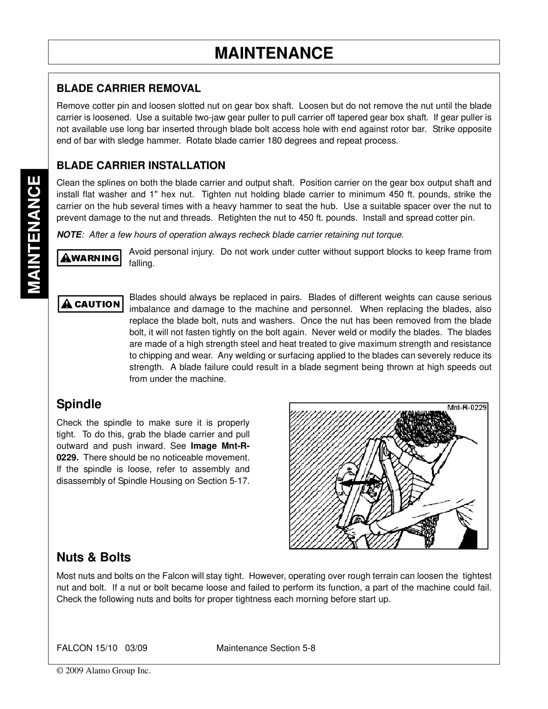
Check the spindle to make sure it is properly tight. To do this, grab the blade carrier and pull outward and push inward. See Image
Nuts & Bolts
Most nuts and bolts on the Falcon will stay tight. However, operating over rough terrain can loosen the tightest nut and bolt. If a nut or bolt became loose and failed to perform its function, a part of the machine could fail. Check the following nuts and bolts for proper tightness each morning before start up.
FALCON 15/10 03/09 | Maintenance Section |
© 2009 Alamo Group Inc.
