Dimensions
|
| R/PR | G/Y | B/PB | SYNC/HD | VD |
|
|
| |
VIDEO IN |
|
| RGB | 1 IN |
|
| RGB 2 IN | LAN | ||
| REMOTE 1 | REMOTE 2 IN |
| IN | SERIAL | OUT |
|
| ||
| IN | OUT |
|
|
|
|
|
|
|
|
|
|
|
|
|
|
|
|
| >PC< | TBMU448 |
86.5
157
167
unit : mm
478.5
368 | 425 | 441 |
4 | 12 |
| ENGLISH |
436
530
Installation dimensions diagram
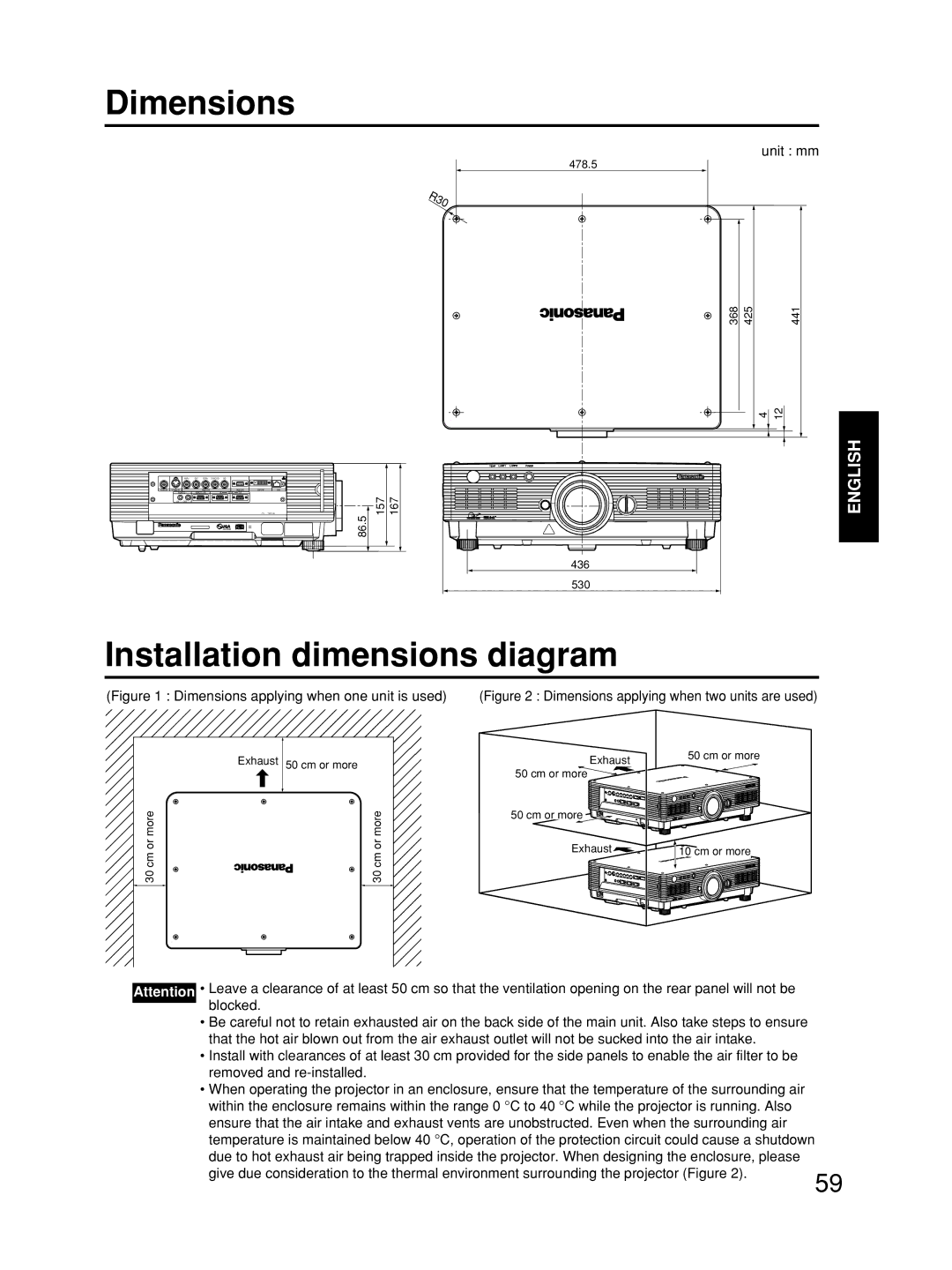
(Figure 1 : Dimensions applying when one unit is used) | (Figure 2 : Dimensions applying when two units are used) |
Exhaust | 50 cm or more |
30 cm or more | 30 cm or more |
Exhaust
50 cm or more
50 cm or more
Exhaust ![]()
50 cm or more
![]() 10 cm or more
10 cm or more
Attention • Leave a clearance of at least 50 cm so that the ventilation opening on the rear panel will not be blocked.
• Be careful not to retain exhausted air on the back side of the main unit. Also take steps to ensure that the hot air blown out from the air exhaust outlet will not be sucked into the air intake.
• Install with clearances of at least 30 cm provided for the side panels to enable the air filter to be removed and
• When operating the projector in an enclosure, ensure that the temperature of the surrounding air within the enclosure remains within the range 0 °C to 40 °C while the projector is running. Also ensure that the air intake and exhaust vents are unobstructed. Even when the surrounding air temperature is maintained below 40 °C, operation of the protection circuit could cause a shutdown due to hot exhaust air being trapped inside the projector. When designing the enclosure, please
give due consideration to the thermal environment surrounding the projector (Figure 2).
59
