Basic Installation/Operation
2 | 3 | 4 |
|
| |
1 |
| 5 |
|
| |
|
| 6 |
|
| 7 |
F
C
![]()
![]() A (BASE)
A (BASE) ![]()
![]()
![]() B (OVERALL)
B (OVERALL)![]()
3
8
E ![]()
![]()
![]()
![]() G (BASE)
G (BASE) ![]()
![]()
![]() D (OVERALL)
D (OVERALL) ![]()
L
M
N
O
10
911
![]() Q
Q ![]()
![]() 16
16
|
| K |
| |
|
|
|
|
|
|
|
| J | |
P |
|
|
| |
|
|
|
|
|
15
H
35 - 125
12
13
14
PHM770N
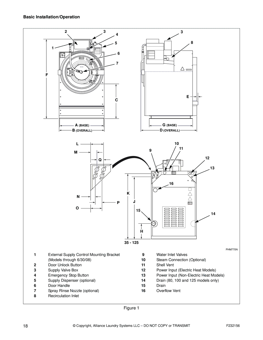
1 | External Supply Control Mounting Bracket | 9 | Water Inlet Valves |
| (Models through 6/30/08) | 10 | Steam Connection (Optional) |
2 | Door Unlock Button | 11 | Shell Vent |
3 | Supply Valve Box | 12 | Power Input (Electric Heat Models) |
4 | Emergency Stop Button | 13 | Power Input |
5 | Supply Dispenser (optional) | 14 | Drain (80, 100 and 125 models only) |
6 | Door Handle | 15 | Drain |
7 | Spray Rinse Nozzle (optional) | 16 | Overflow Vent |
8Recirculation Inlet
Figure 1
18 | © Copyright, Alliance Laundry Systems LLC – DO NOT COPY or TRANSMIT | F232156 |
