Network Topologies
Power
Workgroup
Topology
This section illustrates several of the network topologies you can create with the
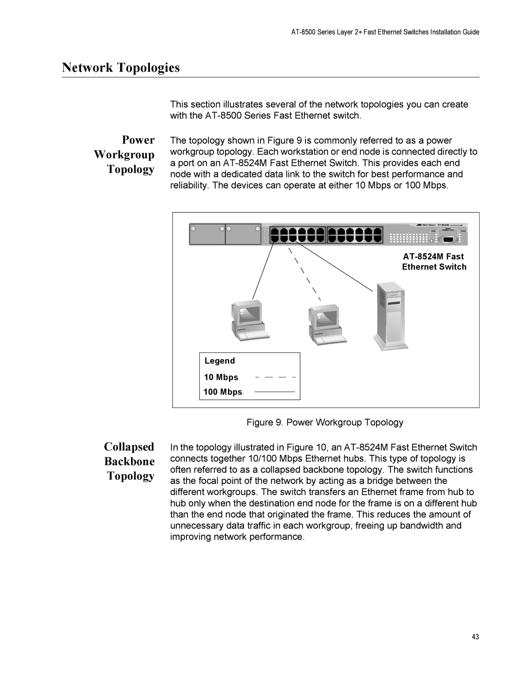
The topology shown in Figure 9 is commonly referred to as a power workgroup topology. Each workstation or end node is connected directly to a port on an
Collapsed
Backbone
Topology
| |
MODE | STATUS |
Ethernet Switch | |
Legend |
|
10 Mbps |
|
100 Mbps |
|
Figure 9. Power Workgroup Topology
In the topology illustrated in Figure 10, an AT-8524M Fast Ethernet Switch connects together 10/100 Mbps Ethernet hubs. This type of topology is often referred to as a collapsed backbone topology. The switch functions as the focal point of the network by acting as a bridge between the different workgroups. The switch transfers an Ethernet frame from hub to hub only when the destination end node for the frame is on a different hub than the end node that originated the frame. This reduces the amount of unnecessary data traffic in each workgroup, freeing up bandwidth and improving network performance.
43