Electronic Functional Description
WARNING
To avoid electrical shock which can cause severe personal injury or death, disconnect power to refrigerator using power switch before servicing. Wires removed during disassembly must be replaced on proper terminals to insure correct earthing and polarization. After servicing, reconnect power using power switch.
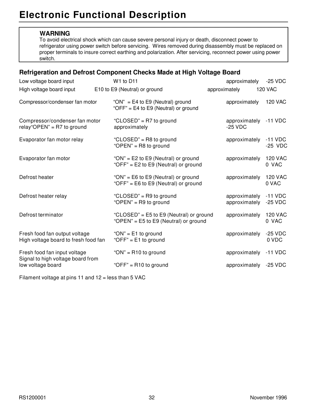
Refrigeration and Defrost Component Checks Made at High Voltage Board
Low voltage board input |
| W1 to D11 |
| approximately | ||
High voltage board input | E10 to E9 (Neutral) or ground | approximately | 120 VAC | |||
Compressor/condenser fan motor | “ON” = E4 to E9 (Neutral) ground |
| approximately | 120 VAC | ||
|
| “OFF”= E4 to E9 (Neutral) or ground |
|
|
|
|
Compressor/condenser fan motor | “CLOSED” = R7 to ground |
| approximately | |||
relay“OPEN” = R7 to ground |
| approximately |
|
|
| |
Evaporator fan motor relay |
| “CLOSED” = R8 to ground |
| approximately | ||
|
| “OPEN” = R8 to ground |
|
|
| |
Evaporator fan motor |
| “ON” = E2 to E9 (Neutral) or ground |
| approximately | 120 VAC | |
|
| “OFF” = E2 to E9 (Neutral) or ground |
|
|
| 0 VAC |
Defrost heater |
| “ON” = E6 to E9 (Neutral) or ground |
| approximately | 120 VAC | |
|
| “OFF” = E6 to E9 (Neutral) or ground |
|
|
| 0 VAC |
Defrost heater relay |
| “CLOSED” = R9 to ground |
| approximately | ||
|
| “OPEN” = R9 to ground |
| approximately | ||
Defrost terminator |
| “CLOSED” = E5 to E9 (Neutral) or ground | approximately | 120 VAC | ||
|
| “OPEN” = E5 to E9 (Neutral) or ground |
|
|
| 0 VAC |
Fresh food fan output voltage |
| “ON” = E1 to ground |
| approximately | ||
High voltage board to fresh food fan | “OFF” = E1 to ground |
|
|
| 0 VDC | |
Fresh food fan input voltage |
| “ON” = R10 to ground |
| approximately | ||
Signal to high voltage board from |
|
|
|
|
| |
low voltage board |
| “OFF” = R10 to ground |
| approximately | ||
Filament voltage at pins 11 and 12 = less than 5 VAC
RS1200001 | 32 | November 1996 |
