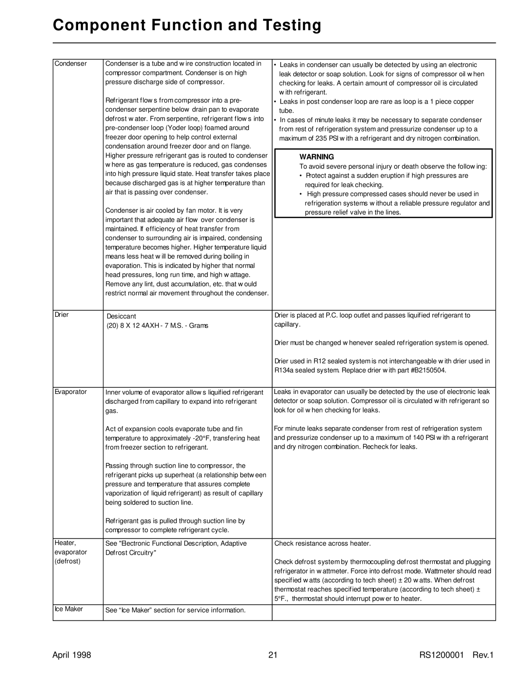
Component Function and Testing
Condenser | Condenser is a tube and w ire construction located in | • | Leaks in condenser can usually be detected by using an electronic | |||
| compressor compartment. Condenser is on high |
|
| leak detector or soap solution. Look for signs of compressor oil w hen | ||
| pressure discharge side of compressor. |
|
| checking for leaks. A certain amount of compressor oil is circulated | ||
| Refrigerant flow s from compressor into a pre- |
|
| w ith refrigerant. | ||
| • | Leaks in post condenser loop are rare as loop is a 1 piece copper | ||||
| condenser serpentine below drain pan to evaporate |
|
| tube. |
|
|
| defrost w ater. From serpentine, refrigerant flow s into | • | In cases of minute leaks it may be necessary to separate condenser | |||
|
|
| from rest of refrigeration system and pressurize condenser up to a | |||
| freezer door opening to help control external |
|
| maximum of 235 PSI w ith a refrigerant and dry nitrogen combination. | ||
| condensation around freezer door and on flange. |
|
|
|
|
|
| Higher pressure refrigerant gas is routed to condenser |
|
| WARNING |
| |
| w here as gas temperature is reduced, gas condenses |
|
| To avoid severe personal injury or death observe the follow ing: |
| |
| into high pressure liquid state. Heat transfer takes place |
|
| • | Protect against a sudden eruption if high pressures are |
|
| because discharged gas is at higher temperature than |
|
|
| required for leak checking. |
|
| air that is passing over condenser. |
|
| • | High pressure compressed cases should never be used in |
|
| Condenser is air cooled by fan motor. It is very |
|
|
| refrigeration systems w ithout a reliable pressure regulator and |
|
|
|
|
| pressure relief valve in the lines. |
| |
| important that adequate air flow over condenser is |
|
|
|
|
|
|
|
|
|
|
| |
| maintained. If efficiency of heat transfer from |
|
|
|
|
|
| condenser to surrounding air is impaired, condensing |
|
|
|
|
|
| temperature becomes higher. Higher temperature liquid |
|
|
|
|
|
| means less heat w ill be removed during boiling in |
|
|
|
|
|
| evaporation. This is indicated by higher that normal |
|
|
|
|
|
| head pressures, long run time, and high w attage. |
|
|
|
|
|
| Remove any lint, dust accumulation, etc. that w ould |
|
|
|
|
|
| restrict normal air movement throughout the condenser. |
|
|
|
|
|
|
|
|
|
| ||
Drier | Desiccant |
| Drier is placed at P.C. loop outlet and passes liquified refrigerant to | |||
| (20) 8 X 12 4AXH - 7 M.S. - Grams |
| capillary. |
|
| |
|
|
| Drier must be changed w henever sealed refrigeration system is opened. | |||
|
|
| Drier used in R12 sealed system is not interchangeable w ith drier used in | |||
|
|
| R134a sealed system. Replace drier w ith part #B2150504. | |||
|
|
|
|
| ||
Evaporator | Inner volume of evaporator allow s liquified refrigerant | Leaks in evaporator can usually be detected by the use of electronic leak | ||||
| discharged from capillary to expand into refrigerant | detector or soap solution. Compressor oil is circulated w ith refrigerant so | ||||
| gas. | look for oil w hen checking for leaks. | ||||
| Act of expansion cools evaporate tube and fin | For minute leaks separate condenser from rest of refrigeration system | ||||
| temperature to approximately | and pressurize condenser up to a maximum of 140 PSI w ith a refrigerant | ||||
| from freezer section to refrigerant. | and dry nitrogen combination. Recheck for leaks. | ||||
| Passing through suction line to compressor, the |
|
|
|
|
|
| refrigerant picks up superheat (a relationship betw een |
|
|
|
|
|
| pressure and temperature that assures complete |
|
|
|
|
|
| vaporization of liquid refrigerant) as result of capillary |
|
|
|
|
|
| being soldered to suction line. |
|
|
|
|
|
| Refrigerant gas is pulled through suction line by |
|
|
|
|
|
| compressor to complete refrigerant cycle. |
|
|
|
|
|
|
|
|
|
| ||
Heater, | See "Electronic Functional Description, Adaptive |
| Check resistance across heater. | |||
evaporator | Defrost Circuitry" |
|
|
|
|
|
(defrost) |
|
| Check defrost system by thermocoupling defrost thermostat and plugging | |||
|
|
| refrigerator in w attmeter. Force into defrost mode. Wattmeter should read | |||
|
|
| specified w atts (according to tech sheet) ± 20 w atts. When defrost | |||
|
|
| thermostat reaches specified temperature (according to tech sheet) ± | |||
|
|
| 5°F., thermostat should interrupt pow er to heater. | |||
|
|
|
|
|
|
|
Ice Maker | See “Ice Maker” section for service information. |
|
|
|
|
|
|
|
|
|
|
|
|
April 1998 | 21 | RS1200001 Rev.1 |
