FIRE SUPPRESSION SYSTEM
(F.S.S.) _____________________
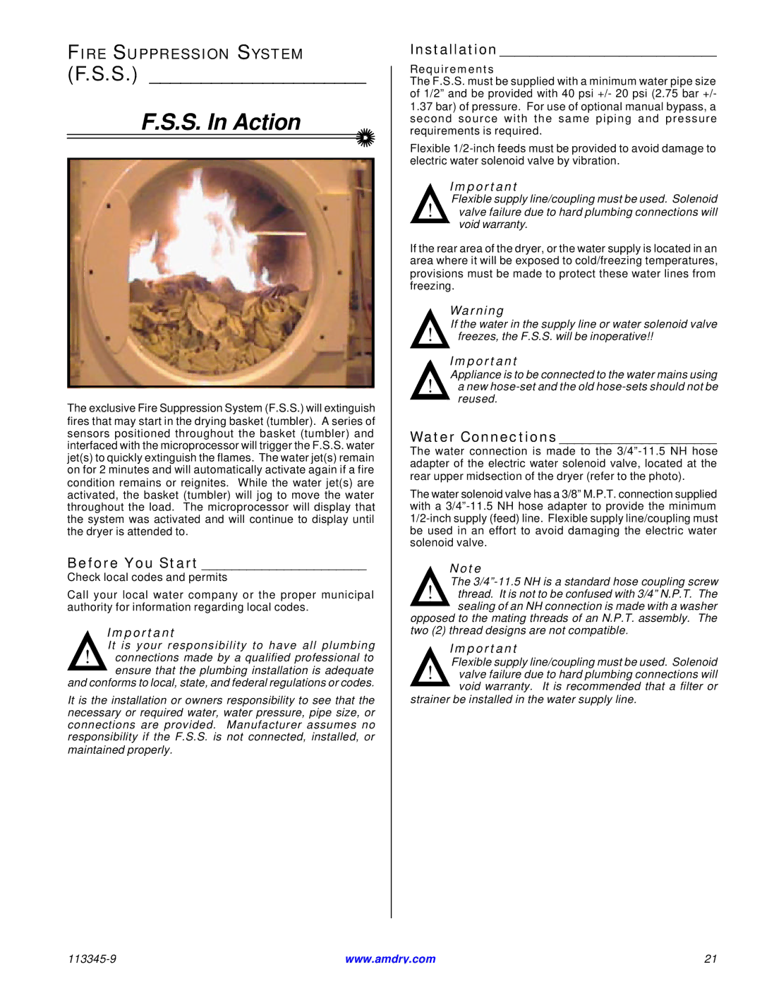
F.S.S. In Action
The exclusive Fire Suppression System (F.S.S.) will extinguish fires that may start in the drying basket (tumbler). A series of sensors positioned throughout the basket (tumbler) and interfaced with the microprocessor will trigger the F.S.S. water jet(s) to quickly extinguish the flames. The water jet(s) remain on for 2 minutes and will automatically activate again if a fire condition remains or reignites. While the water jet(s) are activated, the basket (tumbler) will jog to move the water throughout the load. The microprocessor will display that the system was activated and will continue to display until the dryer is attended to.
Before You Start ______________________
Check local codes and permits
Call your local water company or the proper municipal authority for information regarding local codes.
Important
It is your responsibility to have all plumbing
!connections made by a qualified professional to ![]() ensure that the plumbing installation is adequate and conforms to local, state, and federal regulations or codes.
ensure that the plumbing installation is adequate and conforms to local, state, and federal regulations or codes.
It is the installation or owners responsibility to see that the necessary or required water, water pressure, pipe size, or connections are provided. Manufacturer assumes no responsibility if the F.S.S. is not connected, installed, or maintained properly.
Installation _____________________________
Requirements
The F.S.S. must be supplied with a minimum water pipe size of 1/2” and be provided with 40 psi +/- 20 psi (2.75 bar +/-
1.37bar) of pressure. For use of optional manual bypass, a second source with the same piping and pressure requirements is required.
Flexible
Important
Flexible supply line/coupling must be used. Solenoid
!valve failure due to hard plumbing connections will ![]() void warranty.
void warranty.
If the rear area of the dryer, or the water supply is located in an area where it will be exposed to cold/freezing temperatures, provisions must be made to protect these water lines from freezing.
Warning
If the water in the supply line or water solenoid valve
!freezes, the F.S.S. will be inoperative!!
Important
Appliance is to be connected to the water mains using
!a new ![]() reused.
reused.
Water Connections _____________________
The water connection is made to the
The water solenoid valve has a 3/8” M.P.T. connection supplied with a
Note
The
!thread. It is not to be confused with 3/4” N.P.T. The
![]() sealing of an NH connection is made with a washer opposed to the mating threads of an N.P.T. assembly. The two (2) thread designs are not compatible.
sealing of an NH connection is made with a washer opposed to the mating threads of an N.P.T. assembly. The two (2) thread designs are not compatible.
Important
Flexible supply line/coupling must be used. Solenoid
!valve failure due to hard plumbing connections will ![]() void warranty. It is recommended that a filter or strainer be installed in the water supply line.
void warranty. It is recommended that a filter or strainer be installed in the water supply line.
www.amdry.com | 21 |