| RELAY |
| J2 CONNECTOR |
| OUTPUT RELAY NOTES |
| OUTPUT |
| DESIGNATIONS |
|
|
|
| NC | 1 |
|
|
| MAJOR | C | 2 |
|
|
|
| NO | 3 |
|
|
|
| NC | 4 |
|
|
| MINOR | C | 5 |
|
|
|
| NO | 6 |
|
|
|
| NC | 7 |
|
|
| VERY LOW V | C | 8 |
|
|
|
| NO | 9 |
|
|
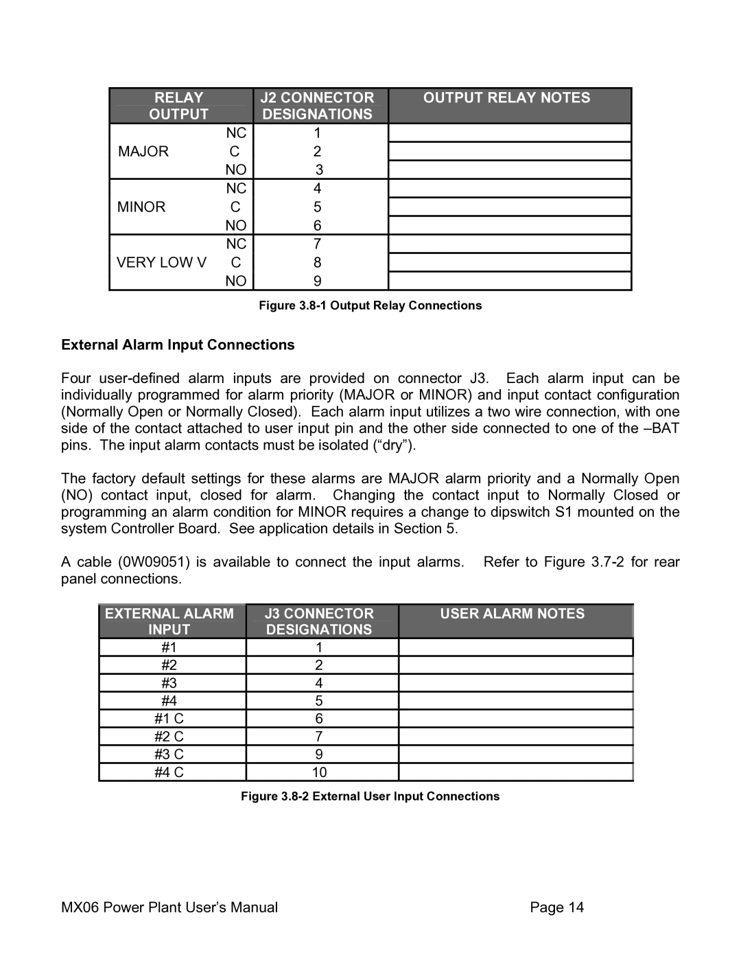
Figure 3.8-1 Output Relay Connections
External Alarm Input Connections
Four
The factory default settings for these alarms are MAJOR alarm priority and a Normally Open (NO) contact input, closed for alarm. Changing the contact input to Normally Closed or programming an alarm condition for MINOR requires a change to dipswitch S1 mounted on the system Controller Board. See application details in Section 5.
A cable (0W09051) is available to connect the input alarms. Refer to Figure
EXTERNAL ALARM | J3 CONNECTOR | USER ALARM NOTES |
INPUT | DESIGNATIONS |
|
#1 | 1 |
|
#2 | 2 |
|
#3 | 4 |
|
#4 | 5 |
|
#1 C | 6 |
|
#2 C | 7 |
|
#3 C | 9 |
|
#4 C | 10 |
|
Figure 3.8-2 External User Input Connections
MX06 Power Plant User’s Manual | Page 14 |
