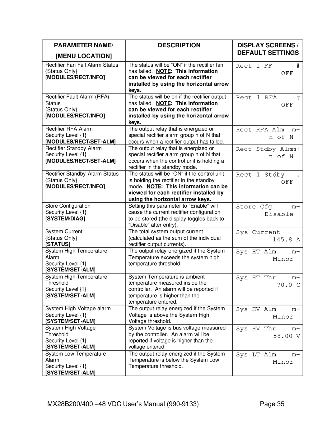
PARAMETER NAME/ | DESCRIPTION | DISPLAY SCREENS / | |
[MENU LOCATION] |
| DEFAULT SETTINGS | |
|
|
| |
|
|
|
|
Rectifier Fan Fail Alarm Status | The status will be “ON” if the rectifier fan | Rect 1 FF | # |
{Status Only} | has failed. NOTE: This information | OFF | |
[MODULES/RECT/INFO] | can be viewed for each rectifier |
|
|
| installed by using the horizontal arrow |
|
|
| keys. |
|
|
Rectifier Fault Alarm (RFA) | The status will be on if the rectifier output | Rect 1 RFA | # |
Status | has failed. NOTE: This information | OFF | |
{Status Only} | can be viewed for each rectifier |
|
|
[MODULES/RECT/INFO] | installed by using the horizontal arrow |
|
|
| keys. |
|
|
Rectifier RFA Alarm | The output relay that is energized or | Rect RFA Alm | m+ |
Security Level {1} | special rectifier alarm group n of N that | n of N | |
| occurs when a rectifier output has failed. |
|
|
Rectifier Standby Alarm | The output relay that is energized or | Rect Stdby Almm+ | |
Security Level {1} | special rectifier alarm group n of N that | n of N | |
| occurs when the control unit is holding a |
|
|
| rectifier in the standby mode. |
|
|
Rectifier Standby Alarm Status | The status will be “ON” if the control unit | Rect 1 Stdby | # |
{Status Only} | is holding the rectifier in the standby | OFF | |
[MODULES/RECT/INFO] | mode. NOTE: This information can be |
|
|
| viewed for each rectifier installed by |
|
|
| using the horizontal arrow keys. |
|
|
Store Configuration | Setting this parameter to “Enable” will | Store Cfg | m+ |
Security Level {1} | cause the current rectifier configuration | Disable | |
[SYSTEM/DIAG] | to be stored (the display toggles back to |
|
|
| “Disable” after entry). |
|
|
System Current | The total system output current | Sys Current | + |
{Status Only} | (calculated as the sum of the individual | 145.8 A | |
[STATUS] | rectifier output currents). |
|
|
System High Temperature | The output relay energized if the System | Sys HT Alm | m+ |
Alarm | Temperature exceeds the system high | Minor | |
Security Level {1} | temperature threshold. |
|
|
|
|
| |
System High Temperature | System Temperature is ambient | Sys HT Thr | m+ |
Threshold | temperature measured inside the | 70.0 C | |
Security Level {1} | controller. An alarm will be reported if |
|
|
temperature is higher than the |
|
| |
| temperature entered. |
|
|
System High Voltage alarm | The output relay energized if the System | Sys HV Alm | m+ |
Security Level {1} | Voltage is above the System High | Minor | |
Voltage threshold. |
|
| |
System High Voltage | System Voltage is bus voltage measured | Sys HV Thr | m+ |
Threshold | by the controller. An alarm will be |
| |
Security Level {1} | reported if voltage is higher than the |
|
|
voltage entered. |
|
| |
System Low Temperature | The output relay energized if the System | Sys LT Alm | m+ |
Alarm | Temperature is below the System Low | Minor | |
Security Level {1} | Temperature threshold. |
|
|
|
|
| |
MX28B200/400 | Page 35 |