Parameter Locations, Descriptions, and Default Values
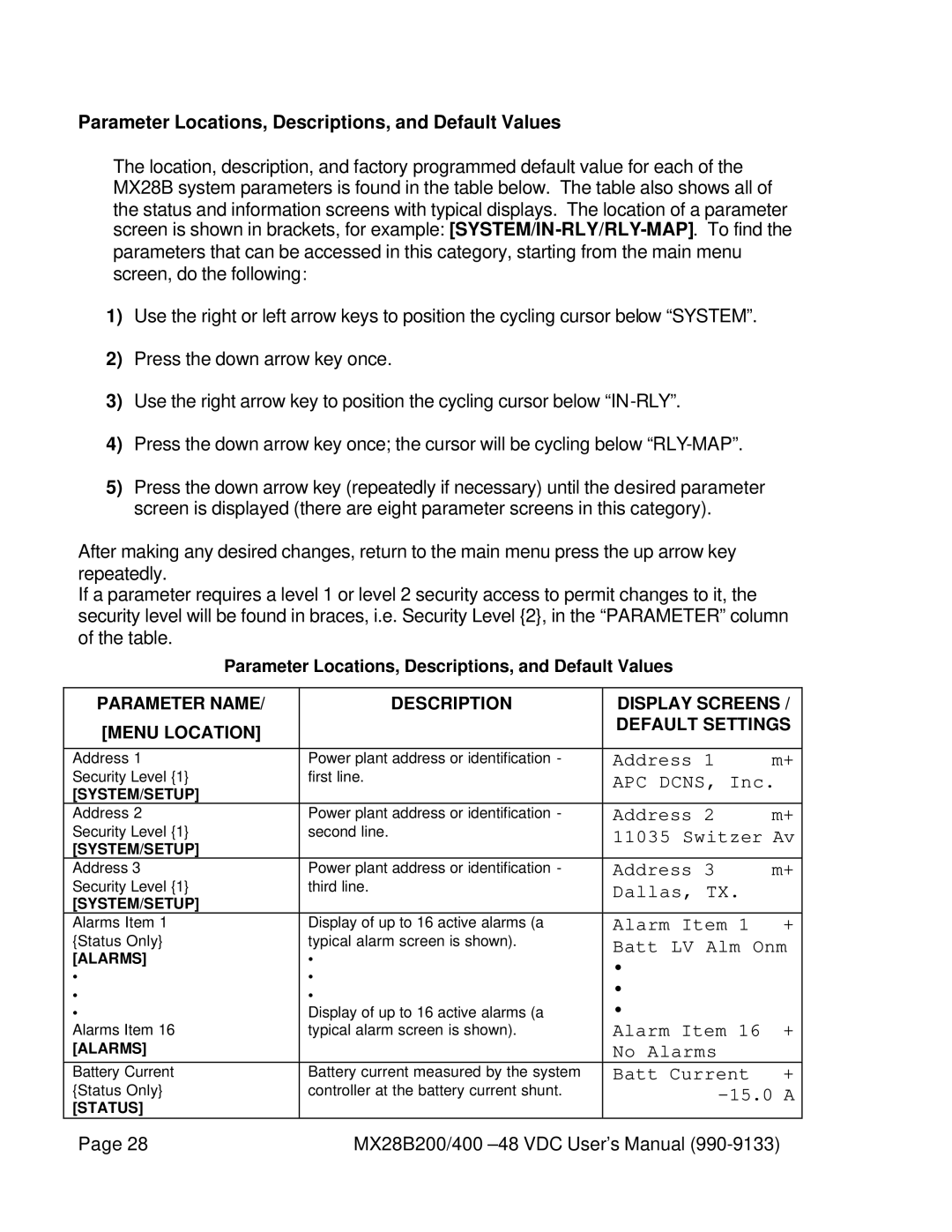
The location, description, and factory programmed default value for each of the MX28B system parameters is found in the table below. The table also shows all of the status and information screens with typical displays. The location of a parameter screen is shown in brackets, for example:
1)Use the right or left arrow keys to position the cycling cursor below “SYSTEM”.
2)Press the down arrow key once.
3)Use the right arrow key to position the cycling cursor below
4)Press the down arrow key once; the cursor will be cycling below
5)Press the down arrow key (repeatedly if necessary) until the desired parameter screen is displayed (there are eight parameter screens in this category).
After making any desired changes, return to the main menu press the up arrow key repeatedly.
If a parameter requires a level 1 or level 2 security access to permit changes to it, the security level will be found in braces, i.e. Security Level {2}, in the “PARAMETER” column of the table.
Parameter Locations, Descriptions, and Default Values
PARAMETER NAME/ | DESCRIPTION | DISPLAY SCREENS / | |
[MENU LOCATION] |
| DEFAULT SETTINGS | |
|
|
| |
|
|
|
|
Address 1 | Power plant address or identification - | Address 1 | m+ |
Security Level {1} | first line. | APC DCNS, Inc. | |
[SYSTEM/SETUP] |
|
|
|
Address 2 | Power plant address or identification - | Address 2 | m+ |
Security Level {1} | second line. | 11035 Switzer Av | |
[SYSTEM/SETUP] |
|
|
|
Address 3 | Power plant address or identification - | Address 3 | m+ |
Security Level {1} | third line. | Dallas, TX. |
|
[SYSTEM/SETUP] |
|
|
|
Alarms Item 1 | Display of up to 16 active alarms (a | Alarm Item 1 | + |
{Status Only} | typical alarm screen is shown). | Batt LV Alm Onm | |
[ALARMS] | • | • |
|
• | • |
| |
• |
| ||
• | • |
| |
• | Display of up to 16 active alarms (a | • | + |
Alarms Item 16 | typical alarm screen is shown). | Alarm Item 16 | |
[ALARMS] |
| No Alarms |
|
Battery Current | Battery current measured by the system | Batt Current | + |
{Status Only} | controller at the battery current shunt. |
| |
[STATUS] |
|
|
|
Page 28 | MX28B200/400 | ||