PARAMETER NAME/ | DESCRIPTION | DISPLAY SCREENS / | |
[MENU LOCATION] |
| DEFAULT SETTINGS | |
|
|
| |
|
|
|
|
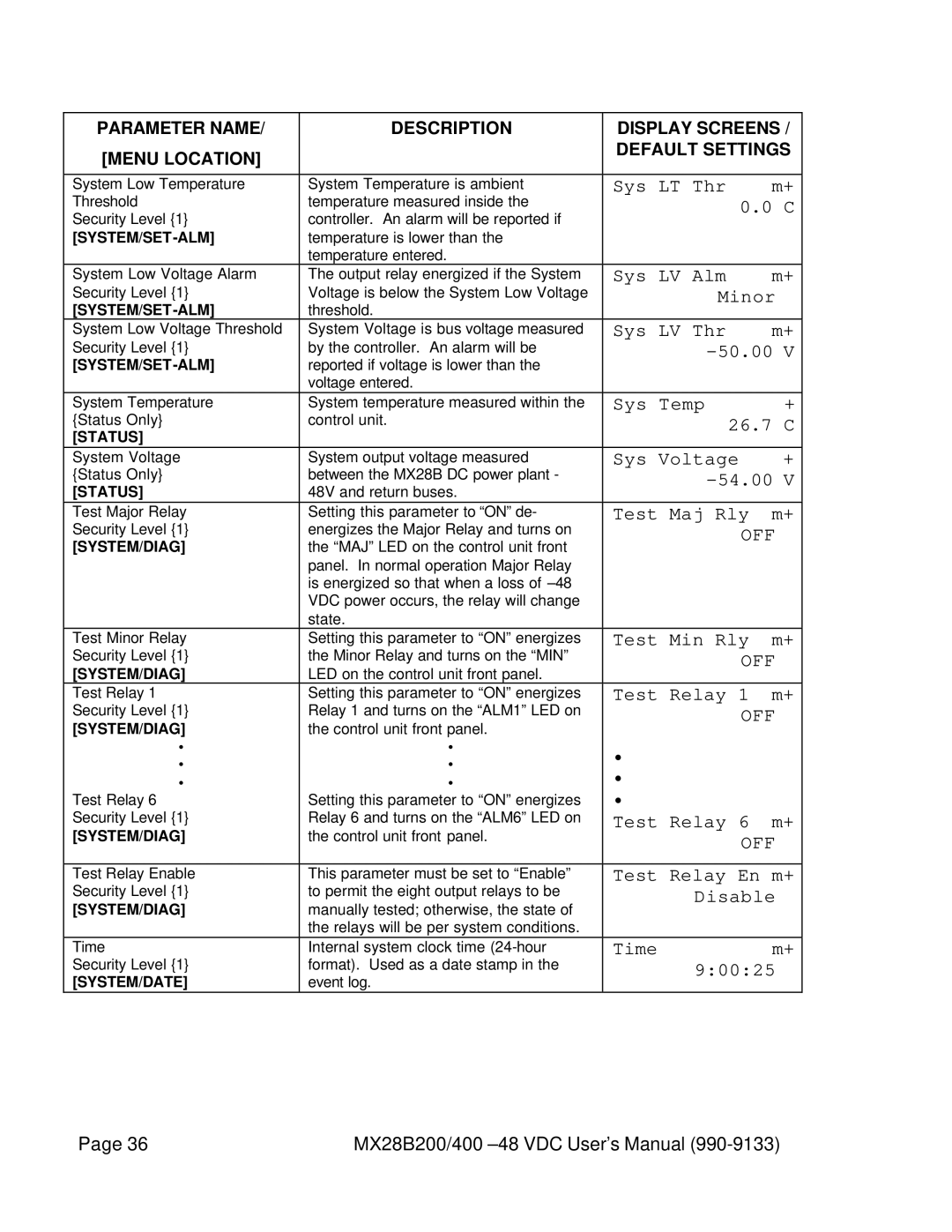
System Low Temperature | System Temperature is ambient | Sys LT Thr | m+ |
Threshold | temperature measured inside the | 0.0 C | |
Security Level {1} | controller. An alarm will be reported if |
|
|
temperature is lower than the |
|
| |
| temperature entered. |
|
|
System Low Voltage Alarm | The output relay energized if the System | Sys LV Alm | m+ |
Security Level {1} | Voltage is below the System Low Voltage | Minor | |
threshold. |
|
| |
System Low Voltage Threshold | System Voltage is bus voltage measured | Sys LV Thr | m+ |
Security Level {1} | by the controller. An alarm will be |
| |
reported if voltage is lower than the |
|
| |
| voltage entered. |
|
|
System Temperature | System temperature measured within the | Sys Temp | + |
{Status Only} | control unit. | 26.7 C | |
[STATUS] |
|
|
|
System Voltage | System output voltage measured | Sys Voltage | + |
{Status Only} | between the MX28B DC power plant - |
| |
[STATUS] | 48V and return buses. |
|
|
Test Major Relay | Setting this parameter to “ON” de- | Test Maj Rly | m+ |
Security Level {1} | energizes the Major Relay and turns on | OFF | |
[SYSTEM/DIAG] | the “MAJ” LED on the control unit front |
|
|
| panel. In normal operation Major Relay |
|
|
| is energized so that when a loss of |
|
|
| VDC power occurs, the relay will change |
|
|
| state. |
|
|
Test Minor Relay | Setting this parameter to “ON” energizes | Test Min Rly | m+ |
Security Level {1} | the Minor Relay and turns on the “MIN” | OFF | |
[SYSTEM/DIAG] | LED on the control unit front panel. |
|
|
Test Relay 1 | Setting this parameter to “ON” energizes | Test Relay 1 | m+ |
Security Level {1} | Relay 1 and turns on the “ALM1” LED on | OFF | |
[SYSTEM/DIAG] | the control unit front panel. |
|
|
• | • | • |
|
• | • |
| |
• | • | • |
|
Test Relay 6 | Setting this parameter to “ON” energizes | • |
|
Security Level {1} | Relay 6 and turns on the “ALM6” LED on | Test Relay 6 | m+ |
[SYSTEM/DIAG] | the control unit front panel. | OFF | |
|
| ||
|
|
| |
Test Relay Enable | This parameter must be set to “Enable” | Test Relay En m+ | |
Security Level {1} | to permit the eight output relays to be | Disable | |
[SYSTEM/DIAG] | manually tested; otherwise, the state of |
|
|
| the relays will be per system conditions. |
|
|
Time | Internal system clock time | Time | m+ |
Security Level {1} | format). Used as a date stamp in the | 9:00:25 | |
[SYSTEM/DATE] | event log. |
|
|
Page 36 | MX28B200/400 |