Description of Operation
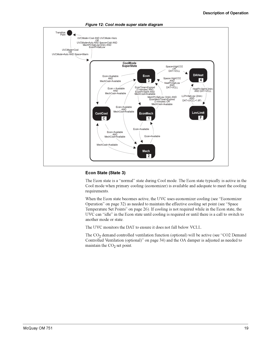
Figure 12: Cool mode super state diagram
Transition
Point
UVCMode≠Cool AND UVCMode≠Auto
OR
UVCMode=Auto AND Space=Cold AND
MechPI=SatLow(3min) AND
EconPI=SatLow
UVCMode=Cool
OR
UVCMode=Auto AND Space=Warm
| CoolMode |
|
| |
| SuperState | Space=HighCO2 | ||
|
|
| OR |
|
|
|
| DAT<VCLL |
|
Econ≠Available | Econ | Space≠HighCO2 | DAHeat | |
| AND | 3 | 4 | |
MechCool≠Available | AND | |||
|
|
| HeatPI=SatLow |
|
|
| EconTimer=Expired | AND |
|
| Econ = Available | DAT>VCLL | HeatPI=SatHi(2min) | |
| (3 minutes) AND |
| ||
| AND | EconPI=SatHi AND |
| AND DAT<VCLL |
MechCool≠Available | MechCool=Available |
| LLPI=SatLow (2min) | |
|
| MechPI=SatLow (3min) AND | ||
|
| AND | ||
|
| EconMechTimer=Expired | ||
|
| DAT>(VCLL+1.8F) | ||
|
| (3 minutes) OR | ||
| Econ≠Available | MechCool≠Available |
| |
|
|
|
| |
| AND |
|
|
|
CantCool | MechCool=Available | EconMech |
| LowLimit |
|
| |||
C1
F
Econ≠Available
Econ≠Available
AND
MechCool=AvailableEcon=Available
MechCool≠Available
Mech
2
Econ State (State 3)
The Econ state is a “normal” state during Cool mode. The Econ state typically is active in the Cool mode when primary cooling (economizer) is available and adequate to meet the cooling requirements.
When the Econ state becomes active, the UVC uses economizer cooling (see “Economizer Operation” on page 32) as needed to maintain the effective cooling set point (see “Space Temperature Set Points” on page 26). If cooling is not required while in the Econ state, the UVC can “idle” in the Econ state until cooling is required or until there is a call to switch to another mode or state.
The UVC monitors the DAT to ensure it does not fall below VCLL.
The CO2 demand controlled ventilation function (optional) will be active (see “CO2 Demand Controlled Ventilation (optional)” on page 34) and the OA damper is adjusted as needed to maintain the CO2 set point.
McQuay OM 751 | 19 |