UVC Input and Output Table
UVC Input and Output Table
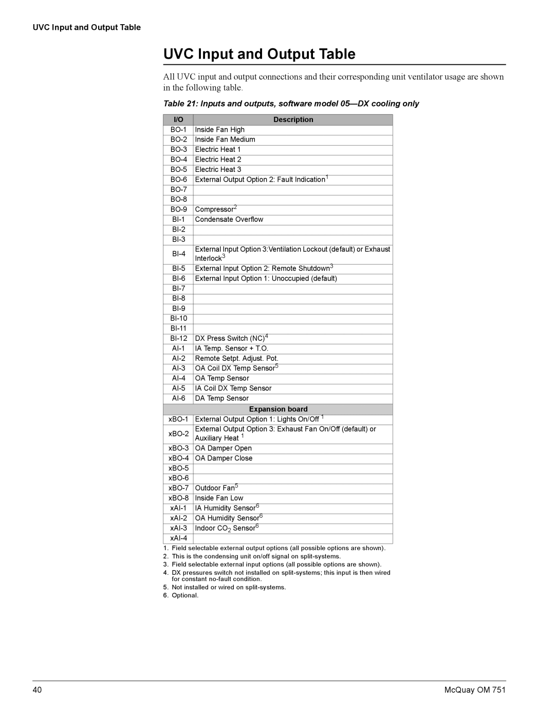
All UVC input and output connections and their corresponding unit ventilator usage are shown in the following table.
Table 21: Inputs and outputs, software model 05—DX cooling only
I/O | Description | |
Inside Fan High | ||
Inside Fan Medium | ||
Electric Heat 1 | ||
Electric Heat 2 | ||
Electric Heat 3 | ||
External Output Option 2: Fault Indication1 | ||
| ||
| ||
Compressor2 | ||
Condensate Overflow | ||
| ||
| ||
External Input Option 3:Ventilation Lockout (default) or Exhaust | ||
Interlock3 | ||
| ||
External Input Option 2: Remote Shutdown3 | ||
External Input Option 1: Unoccupied (default) | ||
| ||
| ||
| ||
| ||
| ||
DX Press Switch (NC)4 | ||
IA Temp. Sensor + T.O. | ||
Remote Setpt. Adjust. Pot. | ||
OA Coil DX Temp Sensor5 | ||
OA Temp Sensor | ||
IA Coil DX Temp Sensor | ||
DA Temp Sensor |
| Expansion board |
External Output Option 1: Lights On/Off 1 | |
External Output Option 3: Exhaust Fan On/Off (default) or | |
Auxiliary Heat 1 | |
OA Damper Open | |
OA Damper Close | |
| |
| |
Outdoor Fan5 | |
Inside Fan Low | |
IA Humidity Sensor6 | |
OA Humidity Sensor6 | |
Indoor CO Sensor6 | |
| 2 |
|
|
1.Field selectable external output options (all possible options are shown).
2.This is the condensing unit on/off signal on
3.Field selectable external input options (all possible options are shown).
4.DX pressures switch not installed on
5.Not installed or wired on
6.Optional.
40 | McQuay OM 751 |
