Getting Started
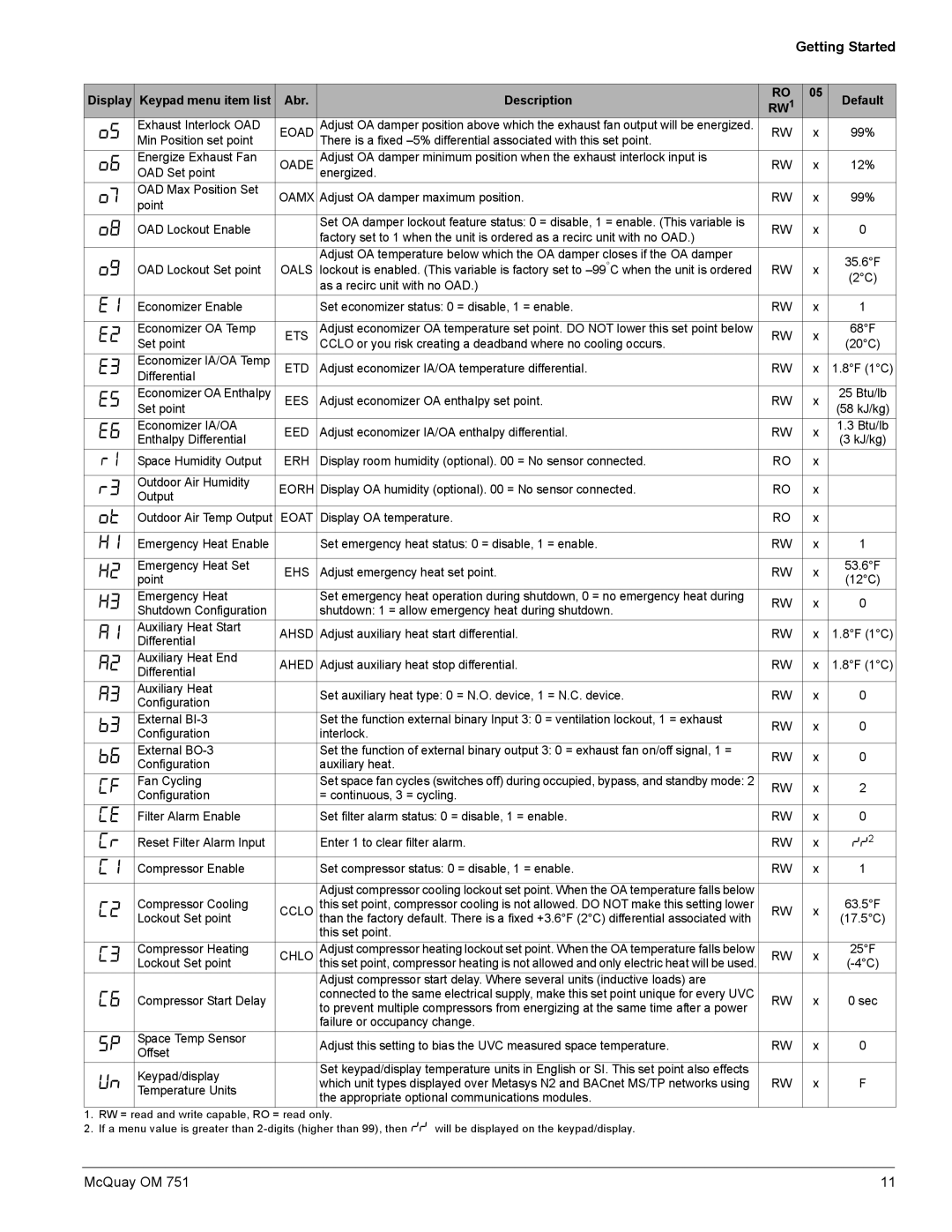
Display | Keypad menu item list | Abr. | Description | RO | 05 | Default | |
RW1 |
| ||||||
|
|
|
|
|
| ||
o5 | Exhaust Interlock OAD | EOAD | Adjust OA damper position above which the exhaust fan output will be energized. | RW | x | 99% | |
Min Position set point | There is a fixed | ||||||
o6 | Energize Exhaust Fan | OADE | Adjust OA damper minimum position when the exhaust interlock input is | RW | x | 12% | |
OAD Set point | energized. | ||||||
o7 | pointOAD Max Position Set | OAMX | Adjust OA damper maximum position. | RW | x | 99% | |
o8 | OAD Lockout Enable |
| Set OA damper lockout feature status: 0 = disable, 1 = enable. (This variable is | RW | x | 0 | |
| factory set to 1 when the unit is ordered as a recirc unit with no OAD.) | ||||||
|
|
|
|
|
| ||
o9 |
|
| Adjust OA temperature below which the OA damper closes if the OA damper |
|
| 35.6°F | |
OAD Lockout Set point | OALS | lockout is enabled. (This variable is factory set to | RW | x | |||
(2°C) | |||||||
|
|
| as a recirc unit with no OAD.) |
|
| ||
|
|
|
|
|
| ||
|
|
|
|
|
|
| |
E1 | Economizer Enable |
| Set economizer status: 0 = disable, 1 = enable. | RW | x | 1 | |
E2 | Economizer OA Temp | ETS | Adjust economizer OA temperature set point. DO NOT lower this set point below | RW | x | 68°F | |
Set point | CCLO or you risk creating a deadband where no cooling occurs. | (20°C) | |||||
E3 | DifferentialEconomizer IA/OA Temp | ETD | Adjust economizer IA/OA temperature differential. | RW | x | 1.8°F (1°C) | |
E5 | Economizer OA Enthalpy | EES | Adjust economizer OA enthalpy set point. | RW | x | 25 Btu/lb | |
Set point | (58 kJ/kg) | ||||||
E6 | Economizer IA/OA | EED | Adjust economizer IA/OA enthalpy differential. | RW | x | 1.3 Btu/lb | |
Enthalpy Differential | (3 kJ/kg) | ||||||
r1 | Space Humidity Output | ERH | Display room humidity (optional). 00 = No sensor connected. | RO | x |
| |
r3 | OutputOutdoor Air Humidity | EORH | Display OA humidity (optional). 00 = No sensor connected. | RO | x |
| |
ot | Outdoor Air Temp Output | EOAT | Display OA temperature. | RO | x |
| |
k1 | Emergency Heat Enable |
| Set emergency heat status: 0 = disable, 1 = enable. | RW | x | 1 | |
k2 | Emergency Heat Set | EHS | Adjust emergency heat set point. | RW | x | 53.6°F | |
point | (12°C) | ||||||
k3 | Emergency Heat |
| Set emergency heat operation during shutdown, 0 = no emergency heat during | RW | x | 0 | |
Shutdown Configuration |
| shutdown: 1 = allow emergency heat during shutdown. | |||||
A1 | Auxiliary Heat Start | AHSD | Adjust auxiliary heat start differential. | RW | x | 1.8°F (1°C) | |
Differential | |||||||
A2 | Auxiliary Heat End | AHED | Adjust auxiliary heat stop differential. | RW | x | 1.8°F (1°C) | |
Differential | |||||||
A3 | Auxiliary Heat |
| Set auxiliary heat type: 0 = N.O. device, 1 = N.C. device. | RW | x | 0 | |
Configuration |
| ||||||
b3 | External |
| Set the function external binary Input 3: 0 = ventilation lockout, 1 = exhaust | RW | x | 0 | |
Configuration |
| interlock. | |||||
b6 | External |
| Set the function of external binary output 3: 0 = exhaust fan on/off signal, 1 = | RW | x | 0 | |
Configuration |
| auxiliary heat. | |||||
(F | Fan Cycling |
| Set space fan cycles (switches off) during occupied, bypass, and standby mode: 2 | RW | x | 2 | |
Configuration |
| = continuous, 3 = cycling. | |||||
(E | Filter Alarm Enable |
| Set filter alarm status: 0 = disable, 1 = enable. | RW | x | 0 | |
(r | Reset Filter Alarm Input |
| Enter 1 to clear filter alarm. | RW | x | //2 | |
(1 | Compressor Enable |
| Set compressor status: 0 = disable, 1 = enable. | RW | x | 1 | |
|
|
| Adjust compressor cooling lockout set point. When the OA temperature falls below |
|
|
| |
(2 | Compressor Cooling | CCLO | this set point, compressor cooling is not allowed. DO NOT make this setting lower | RW | x | 63.5°F | |
Lockout Set point | than the factory default. There is a fixed +3.6°F (2°C) differential associated with | (17.5°C) | |||||
|
|
| this set point. |
|
|
| |
(3 | Compressor Heating | CHLO | Adjust compressor heating lockout set point. When the OA temperature falls below | RW | x | 25°F | |
Lockout Set point | this set point, compressor heating is not allowed and only electric heat will be used. | ||||||
|
|
| Adjust compressor start delay. Where several units (inductive loads) are |
|
|
| |
(6 | Compressor Start Delay |
| connected to the same electrical supply, make this set point unique for every UVC | RW | x | 0 sec | |
| to prevent multiple compressors from energizing at the same time after a power | ||||||
|
|
| failure or occupancy change. |
|
|
| |
SP | OffsetSpace Temp Sensor |
| Adjust this setting to bias the UVC measured space temperature. | RW | x | 0 | |
Un | Keypad/display |
| Set keypad/display temperature units in English or SI. This set point also effects |
|
|
| |
| which unit types displayed over Metasys N2 and BACnet MS/TP networks using | RW | x | F | |||
Temperature Units |
| ||||||
|
|
| the appropriate optional communications modules. |
|
|
|
1.RW = read and write capable, RO = read only.
2.If a menu value is greater than
McQuay OM 751 | 11 |