Diagrams
CCB - Central Control Board Layout
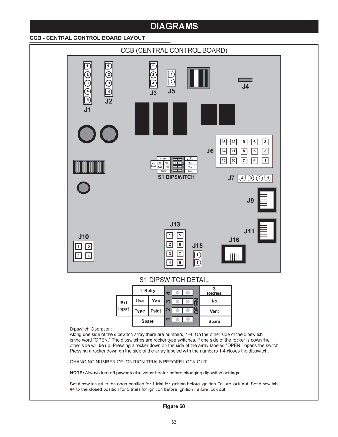
CCB (CENTRAL CONTROL BOARD)
1 | 1 |
22
33
44
5J2
J1
1
21
42
J3 J5
| 1 Retry | 4 |
| 3 | |
|
| Retries | |||
|
|
| OPEN | ||
Ext | Use | Yes | 2 3 | No | |
Input | Type | Tstat | Vent | ||
| Spare | 1 |
| Spare | |
|
|
| |||
S1 DIPSWITCH
J4 |
| 15 | 12 | 9 | 6 |
| 3 |
J6 | 14 | 11 | 8 | 5 |
| 2 |
| 13 | 10 | 7 | 4 |
| 1 |
|
|
|
|
|
|
|
|
| J7 |
|
|
|
|
|
| 4 | 3 | 2 | 1 |
J10
1 | 3 |
2 | 4 |
|
|
| J9 | |
J13 |
| J11 | ||
1 | 5 |
| ||
| J16 | |||
2 | 6 | J15 | ||
| ||||
|
| |||
3 | 7 | 1 |
| |
4 | 8 | 2 |
| |
| S1 DIPSWITCH DETAIL | ||||
| 1 Retry | 4 |
| 3 | |
|
| Retries | |||
|
|
| OPEN | ||
Ext | Use | Yes | 2 3 | No | |
|
|
| |||
Input | Type | Tstat | Vent | ||
| Spare | 1 |
| Spare | |
|
|
| |||
Dipswitch Operation:
Along one side of the dipswitch array there are numbers,
is the word “OPEN.” The dipswitches are rocker type switches, if one side of the rocker is down the other side will be up. Pressing a rocker down on the side of the array labeled “OPEN,” opens the switch. Pressing a rocker down on the side of the array labeled with the numbers
CHANGING NUMBER OF IGNITION TRIALS BEFORE LOCK OUT
NOTE: Always turn off power to the water heater before changing dipswitch settings.
Set dipswitch #4 to the open position for 1 trial for ignition before Ignition Failure lock out. Set dipswitch #4 to the closed position for 3 trials for ignition before Ignition Failure lock out.
Figure 60
63