Top View
7 | 8 | 9 | 10 |
6 |
|
| |
|
| 11 | |
|
|
| |
|
|
| 12 |
5 |
|
| 13 |
4 |
|
| 2 |
3 |
|
|
|
2 |
|
| 14 |
|
|
| 15 |
FRONT |
|
| 16 |
1 |
|
| |
| 18 | 17 | |
|
|
|
Figure 3
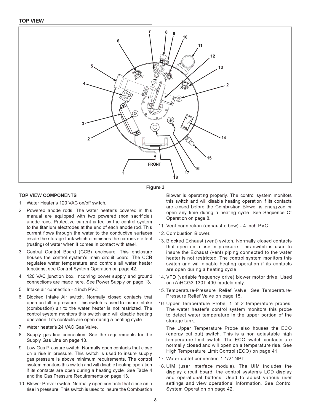
Top View Components
1.Water Heater’s 120 VAC on/off switch.
2.Powered anode rods. The water heater’s covered in this manual are equipped with two powered (non sacrificial) anode rods. Protective current is fed by the control system to the titanium electrodes at the end of each anode rod. This current flows through the water to the conductive surfaces inside the storage tank which diminishes the corrosive effect (rusting) of water when it comes in contact with steel.
3.Central Control Board (CCB) enclosure. This enclosure houses the control system’s main circuit board. The CCB regulates water temperature and controls all water heater functions, see Control System Operation on page 42.
4.120 VAC junction box. Incoming power supply and ground connections are made here. See Power Supply on page 13.
5.Intake air connection - 4 inch PVC.
6.Blocked Intake Air switch. Normally closed contacts that open on fall in pressure. This switch is used to insure intake (combustion) air to the water heater is not restricted. The control system monitors this switch and will disable heating operation if its contacts are open during a heating cycle.
7.Water heater's 24 VAC Gas Valve.
8.Supply gas line connection. See the requirements for the Supply Gas Line on page 13.
9.Low Gas Pressure switch. Normally open contacts that close on a rise in pressure. This switch is used to insure supply gas pressure is above minimum requirements. The control system monitors this switch and will disable heating operation if its contacts are open during a heating cycle. See Table 4 and the Gas Pressure Requirements on page 13.
10.Blower Prover switch. Normally open contacts that close on a rise in pressure. This switch is used to insure the Combustion
Blower is operating properly. The control system monitors this switch and will disable heating operation if its contacts are closed before the Combustion Blower is energized or open any time during a heating cycle. See Sequence Of Operation on page 8.
11.Vent connection (exhaust elbow) - 4 inch PVC.
12.Combustion Blower.
13.Blocked Exhaust (vent) switch. Normally closed contacts that open on a rise in pressure. This switch is used to insure the Exhaust (vent) piping connected to the water heater is not restricted. The control system monitors this switch and will disable heating operation if its contacts are open during a heating cycle.
14.VFD (variable frequency drive) blower motor drive. Used on (A)HCG3 130T 400 models only.
15.
16.Upper Temperature Probe, 1 of 2 temperature probes. The water heater’s control system monitors this probe to detect water temperature in the upper portion of the storage tank.
The Upper Temperature Probe also houses the ECO
(energy cut out) switch. This is a non adjustable high temperature limit switch. The ECO switch contacts are normally closed and will open on a temperature rise. See High Temperature Limit Control (ECO) on page 41.
17.Water outlet connection 1 1/2” NPT.
18.UIM (user interface module). The UIM includes the display circuit board, the control system’s LCD display and operational buttons. Used to adjust various user settings and view operational information. See Control System Operation on page 42.
8