Installation Requirements
Gas Pressure Requirements
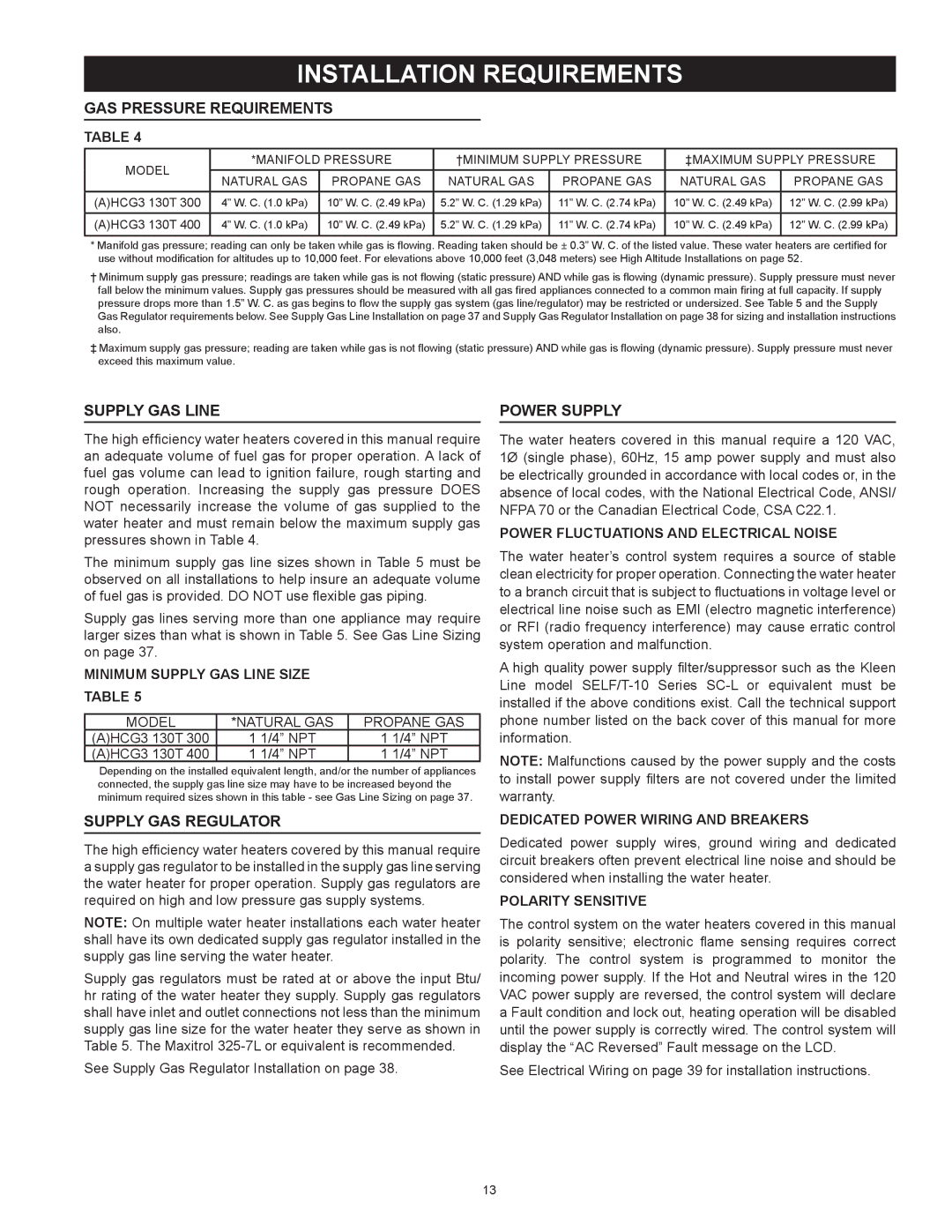
Table 4
Model | *Manifold Pressure | †Minimum Supply Pressure | ‡Maximum Supply Pressure | ||||
NATURAL GAS | PROPANE GAS | NATURAL GAS | PROPANE GAS | NATURAL GAS | PROPANE GAS | ||
| |||||||
|
|
|
|
|
|
| |
(A)HCG3 130T 300 | 4” W. C. (1.0 kPa) | 10” W. C. (2.49 kPa) | 5.2” W. C. (1.29 kPa) | 11” W. C. (2.74 kPa) | 10” W. C. (2.49 kPa) | 12” W. C. (2.99 kPa) | |
(A)HCG3 130T 400 | 4” W. C. (1.0 kPa) | 10” W. C. (2.49 kPa) | 5.2” W. C. (1.29 kPa) | 11” W. C. (2.74 kPa) | 10” W. C. (2.49 kPa) | 12” W. C. (2.99 kPa) | |
*Manifold gas pressure; reading can only be taken while gas is flowing. Reading taken should be ± 0.3” W. C. of the listed value. These water heaters are certified for use without modification for altitudes up to 10,000 feet. For elevations above 10,000 feet (3,048 meters) see High Altitude Installations on page 52.
†Minimum supply gas pressure; readings are taken while gas is not flowing (static pressure) AND while gas is flowing (dynamic pressure). Supply pressure must never fall below the minimum values. Supply gas pressures should be measured with all gas fired appliances connected to a common main firing at full capacity. If supply pressure drops more than 1.5” W. C. as gas begins to flow the supply gas system (gas line/regulator) may be restricted or undersized. See Table 5 and the Supply Gas Regulator requirements below. See Supply Gas Line Installation on page 37 and Supply Gas Regulator Installation on page 38 for sizing and installation instructions also.
‡Maximum supply gas pressure; reading are taken while gas is not flowing (static pressure) AND while gas is flowing (dynamic pressure). Supply pressure must never exceed this maximum value.
Supply Gas Line
The high efficiency water heaters covered in this manual require an adequate volume of fuel gas for proper operation. A lack of fuel gas volume can lead to ignition failure, rough starting and rough operation. Increasing the supply gas pressure does not necessarily increase the volume of gas supplied to the water heater and must remain below the maximum supply gas pressures shown in Table 4.
The minimum supply gas line sizes shown in Table 5 must be observed on all installations to help insure an adequate volume of fuel gas is provided. Do not use flexible gas piping.
Supply gas lines serving more than one appliance may require larger sizes than what is shown in Table 5. See Gas Line Sizing on page 37.
MINIMUM SUPPLY GAS LINE SIZE
Table 5
MODEL | *NATURAL GAS | PROPANE GAS |
(A)HCG3 130T 300 | 1 1/4” NPT | 1 1/4” NPT |
(A)HCG3 130T 400 | 1 1/4” NPT | 1 1/4” NPT |
Depending on the installed equivalent length, and/or the number of appliances connected, the supply gas line size may have to be increased beyond the minimum required sizes shown in this table - see Gas Line Sizing on page 37.
Supply Gas Regulator
The high efficiency water heaters covered by this manual require a supply gas regulator to be installed in the supply gas line serving the water heater for proper operation. Supply gas regulators are required on high and low pressure gas supply systems.
Note: On multiple water heater installations each water heater shall have its own dedicated supply gas regulator installed in the supply gas line serving the water heater.
Supply gas regulators must be rated at or above the input Btu/ hr rating of the water heater they supply. Supply gas regulators shall have inlet and outlet connections not less than the minimum supply gas line size for the water heater they serve as shown in Table 5. The Maxitrol
See Supply Gas Regulator Installation on page 38.
Power Supply
The water heaters covered in this manual require a 120 VAC, 1Ø (single phase), 60Hz, 15 amp power supply and must also be electrically grounded in accordance with local codes or, in the absence of local codes, with the National Electrical Code, ANSI/ NFPA 70 or the Canadian Electrical Code, CSA C22.1.
Power Fluctuations and Electrical Noise
The water heater’s control system requires a source of stable clean electricity for proper operation. Connecting the water heater to a branch circuit that is subject to fluctuations in voltage level or electrical line noise such as EMI (electro magnetic interference) or RFI (radio frequency interference) may cause erratic control system operation and malfunction.
A high quality power supply filter/suppressor such as the Kleen Line model
Note: Malfunctions caused by the power supply and the costs to install power supply filters are not covered under the limited warranty.
Dedicated Power Wiring and Breakers
Dedicated power supply wires, ground wiring and dedicated circuit breakers often prevent electrical line noise and should be considered when installing the water heater.
Polarity Sensitive
The control system on the water heaters covered in this manual is polarity sensitive; electronic flame sensing requires correct polarity. The control system is programmed to monitor the incoming power supply. If the Hot and Neutral wires in the 120 VAC power supply are reversed, the control system will declare a Fault condition and lock out, heating operation will be disabled until the power supply is correctly wired. The control system will display the “AC Reversed” Fault message on the LCD.
See Electrical Wiring on page 39 for installation instructions.
13