Chapter 6 Communications Modules | SMART I/O User’s Manual | |||
|
|
|
|
|
|
|
|
|
|
6.2.5 Functional Description
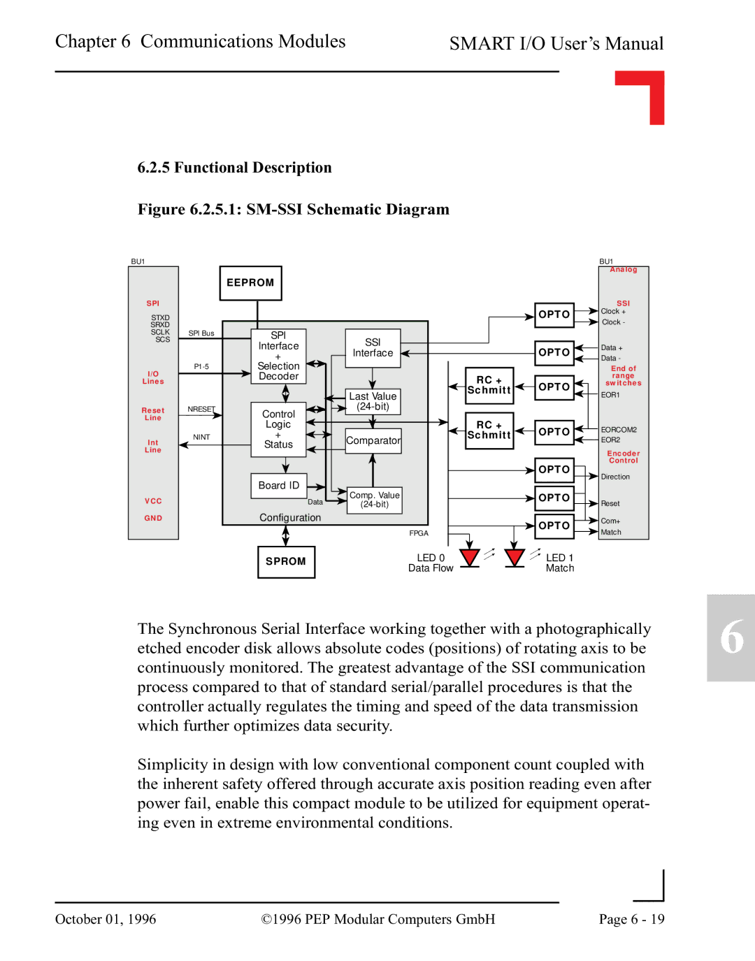
Figure 6.2.5.1: SM-SSI Schematic Diagram
BU1 |
|
|
|
|
| BU1 | |
|
|
|
|
|
| Analog | |
|
| EEPROM |
|
|
|
| |
SPI |
|
|
|
|
| SSI | |
STXD |
|
|
|
| OPTO | Clock + | |
|
|
|
| Clock - | |||
SRXD |
|
|
|
|
| ||
SCLK | SPI Bus | SPI |
|
|
|
| |
SCS |
| Interface | SSI |
|
| Data + | |
|
| Interface |
| OPTO | |||
|
| + |
| Data - | |||
|
|
|
|
| |||
I/O | Selection |
|
|
| End of | ||
| Decoder |
| RC + |
| range | ||
Lines |
|
|
| OPTO | switches | ||
|
|
| Last Value | Schmitt | EOR1 | ||
|
|
|
|
| |||
Reset | NRESET | Control |
|
|
| ||
Line |
|
|
|
|
| ||
| Logic |
| RC + |
|
| ||
|
|
| OPTO | EORCOM2 | |||
| NINT | + |
| Schmitt | |||
Int | Comparator | EOR2 | |||||
| Status |
|
| ||||
Line |
|
|
|
| Encoder | ||
|
|
|
|
|
| ||
|
|
|
|
| OPTO | Control | |
|
|
|
|
| Direction | ||
|
| Board ID |
|
|
| ||
|
| Comp. Value |
| OPTO |
| ||
VCC |
| Data |
|
| |||
|
|
| Reset | ||||
GND |
| Configuration |
|
| OPTO | Com+ | |
|
|
| FPGA |
| Match | ||
|
|
|
|
|
SPROM | LED 0 | LED 1 | |
Data Flow | Match | ||
|
The Synchronous Serial Interface working together with a photographically etched encoder disk allows absolute codes (positions) of rotating axis to be continuously monitored. The greatest advantage of the SSI communication process compared to that of standard serial/parallel procedures is that the controller actually regulates the timing and speed of the data transmission which further optimizes data security.
Simplicity in design with low conventional component count coupled with the inherent safety offered through accurate axis position reading even after power fail, enable this compact module to be utilized for equipment operat- ing even in extreme environmental conditions.
6
|
|
|
|
October 01, 1996 | ©1996 PEP Modular Computers GmbH | Page 6 - 19 | |
|
| ||