Chapter 4 Digital Modules | SMART I/O User’s Manual | |||
|
|
|
|
|
|
|
|
|
|
4.3.5 Functional Description
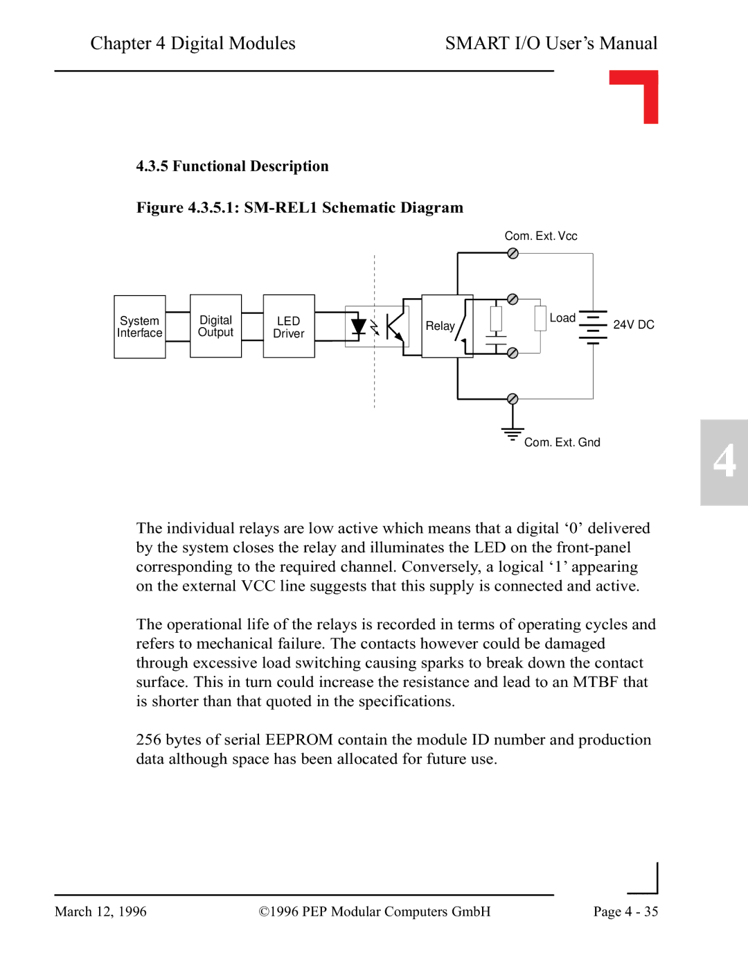
Figure 4.3.5.1: SM-REL1 Schematic Diagram
Com. Ext. Vcc
System
Interface
Digital Output
LED
Driver
Relay![]()
Load
24V DC
Com. Ext. Gnd
4
The individual relays are low active which means that a digital ‘0’ delivered by the system closes the relay and illuminates the LED on the
The operational life of the relays is recorded in terms of operating cycles and refers to mechanical failure. The contacts however could be damaged through excessive load switching causing sparks to break down the contact surface. This in turn could increase the resistance and lead to an MTBF that is shorter than that quoted in the specifications.
256 bytes of serial EEPROM contain the module ID number and production data although space has been allocated for future use.
|
|
|
|
March 12, 1996 | ©1996 PEP Modular Computers GmbH | Page 4 - 35 | |
|
| ||