Chapter 6 Communications Modules | SMART I/O User’s Manual |
| | | | |
| | | | |
6.1.5 Functional Description
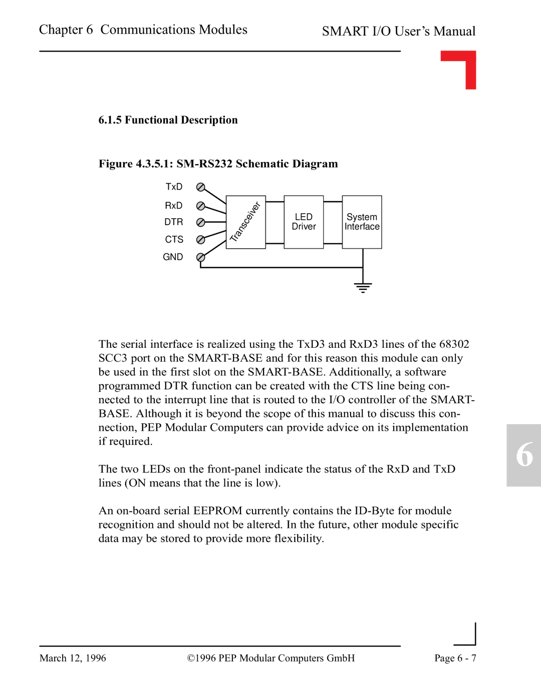
Figure 4.3.5.1: SM-RS232 Schematic Diagram
The serial interface is realized using the TxD3 and RxD3 lines of the 68302 SCC3 port on the SMART-BASE and for this reason this module can only be used in the first slot on the SMART-BASE. Additionally, a software programmed DTR function can be created with the CTS line being con- nected to the interrupt line that is routed to the I/O controller of the SMART- BASE. Although it is beyond the scope of this manual to discuss this con- nection, PEP Modular Computers can provide advice on its implementation
if required.6 The two LEDs on the front-panel indicate the status of the RxD and TxD
lines (ON means that the line is low).
An on-board serial EEPROM currently contains the ID-Byte for module recognition and should not be altered. In the future, other module specific data may be stored to provide more flexibility.
| | | |
March 12, 1996 | ©1996 PEP Modular Computers GmbH | Page 6 - 7 |
| |