SMART I/O User’s Manual | Chapter 5 Analog Modules | |||
|
|
|
|
|
|
|
|
|
|
5.3.6 Configuration
Jumper J1 - EEPROM Protection
Jumper S e t t i n g s | Description | |
J1 | set | EEPROM is not hardware write protected |
| open | EEPROM is hardware write protected |
5.3.7 Pinouts
Screw Terminal Pinouts
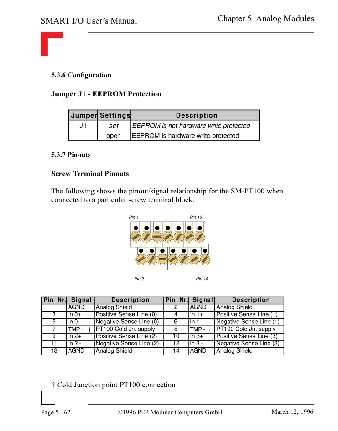
The following shows the pinout/signal relationship for the
Pin 1 | Pin 13 |
Pin 2Pin 14
Pin Nr. | Signal | Description | Pin Nr. | Signal | Description | ||
1 | AGND | † | Analog Shield | 2 | AGND | † | Analog Shield |
3 | In 0+ | Positive Sense Line (0) | 4 | In 1+ | Positive Sense Line (1) | ||
5 | In 0 - | Negative Sense Line (0) | 6 | In 1 - | Negative Sense Line (1) | ||
7 | TMP + | PT100 Cold Jn. supply | 8 | TMP - | PT100 Cold Jn. supply | ||
9 | In 2+ |
| Positive Sense Line (2) | 10 | In 3+ |
| Positive Sense Line (3) |
11 | In 2 - |
| Negative Sense Line (2) | 12 | In 3 - |
| Negative Sense Line (3) |
13 | AGND |
| Analog Shield | 14 | AGND |
| Analog Shield |
† Cold Junction point PT100 connection
|
|
|
|
Page | 5 - 62 | ©1996 PEP Modular Computers GmbH | March 12, 1996 |
|
|
|
