SMART I/O User’s Manual | Chapter 5 Analog Modules | |||
|
|
|
|
|
|
|
|
|
|
5.4.6 Configuration
Although the
Jumper J4 likewise should not be interfered with as it is factory set at the time of ordering and controls the unipolar/bipolar mode of ADC operation .
5.4.7 Pinouts
Screw Terminal Pinouts
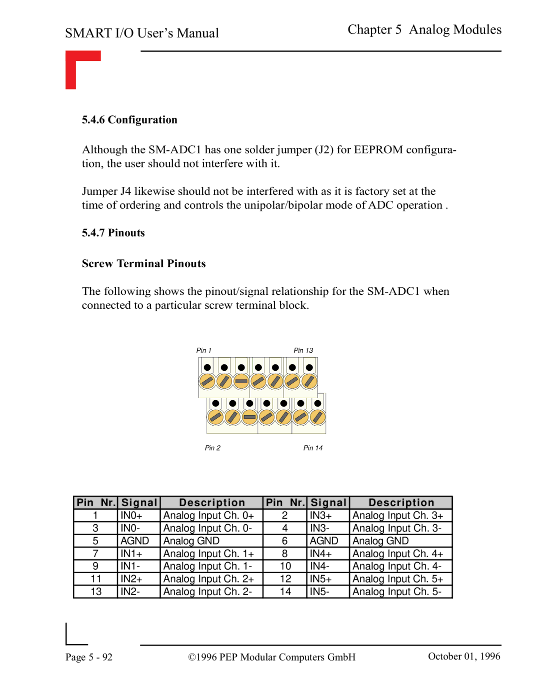
The following shows the pinout/signal relationship for the
Pin 1 | Pin 13 |
Pin 2 | Pin 14 |
Pin Nr. Signal | Description | Pin Nr. Signal | Description | ||
1 | IN0+ | Analog Input Ch. 0+ | 2 | IN3+ | Analog Input Ch. 3+ |
3 | IN0- | Analog Input Ch. 0- | 4 | IN3- | Analog Input Ch. 3- |
5 | AGND | Analog GND | 6 | AGND | Analog GND |
7 | IN1+ | Analog Input Ch. 1+ | 8 | IN4+ | Analog Input Ch. 4+ |
9 | IN1- | Analog Input Ch. 1- | 10 | IN4- | Analog Input Ch. 4- |
11 | IN2+ | Analog Input Ch. 2+ | 12 | IN5+ | Analog Input Ch. 5+ |
13 | IN2- | Analog Input Ch. 2- | 14 | IN5- | Analog Input Ch. 5- |
|
|
|
|
Page | 5 - 92 | ©1996 PEP Modular Computers GmbH | October 01, 1996 |
|
|
|