SMART I/O User’s Manual | Chapter 5 Analog Modules | |||
|
|
|
|
|
|
|
|
|
|
5.5.6 Configuration
Although the
5.5.7 Pinouts
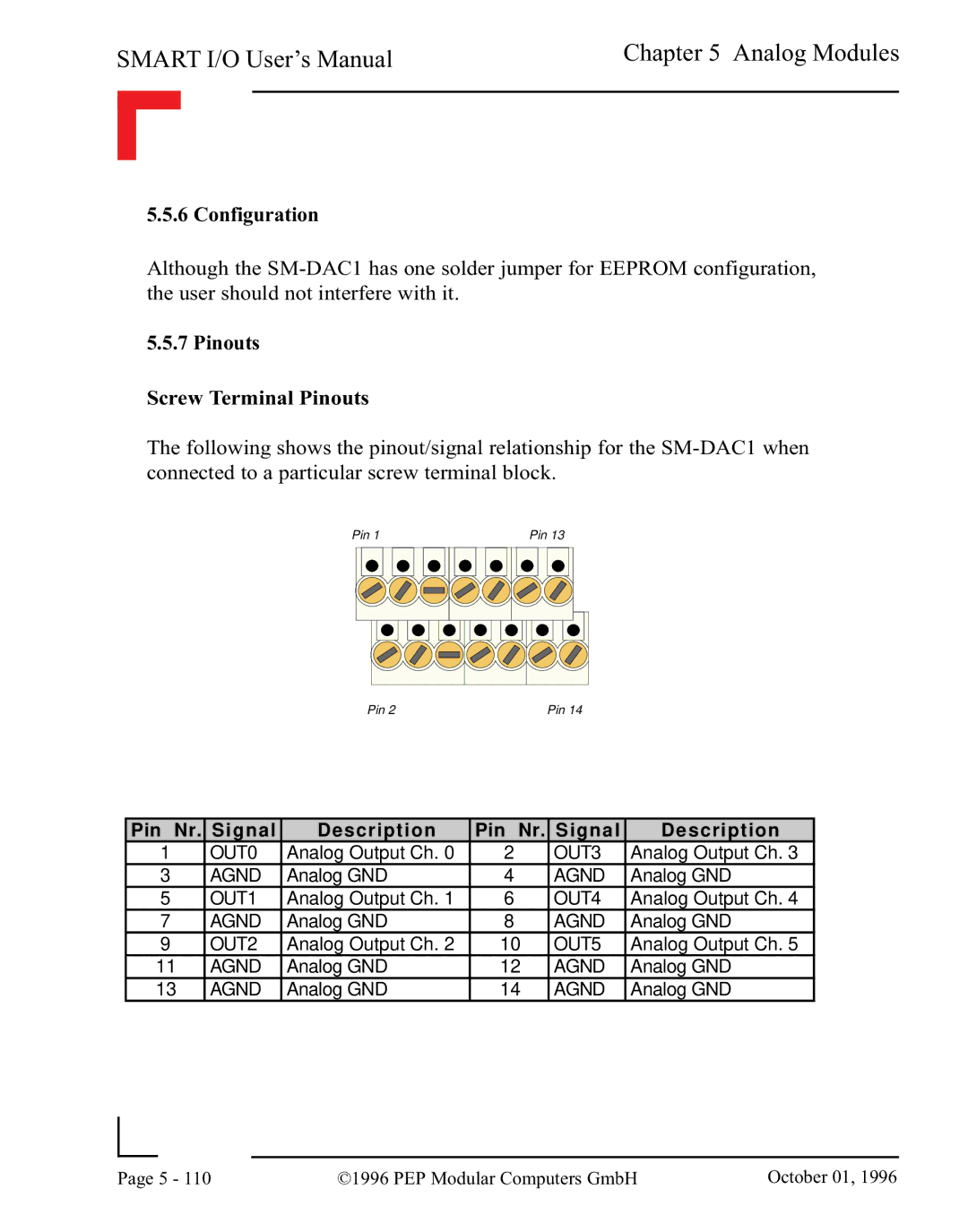
Screw Terminal Pinouts
The following shows the pinout/signal relationship for the
Pin 1 | Pin 13 |
Pin 2 | Pin 14 |
Pin Nr. Signal | Description | Pin Nr. Signal | Description | ||
1 | OUT0 | Analog Output Ch. 0 | 2 | OUT3 | Analog Output Ch. 3 |
3 | AGND | Analog GND | 4 | AGND | Analog GND |
5 | OUT1 | Analog Output Ch. 1 | 6 | OUT4 | Analog Output Ch. 4 |
7 | AGND | Analog GND | 8 | AGND | Analog GND |
9 | OUT2 | Analog Output Ch. 2 | 10 | OUT5 | Analog Output Ch. 5 |
11 | AGND | Analog GND | 12 | AGND | Analog GND |
13 | AGND | Analog GND | 14 | AGND | Analog GND |
|
|
|
|
Page | 5 - 110 | ©1996 PEP Modular Computers GmbH | October 01, 1996 |
|
|
|