Pepper Computer RS232, RS485 user manual SMART-EXT Block Diagram

Models: RS485 RS232

1 320
Download 320 pages 36.43 Kb
Page 83
Image 83

Chapter 3 SMART-EXT

SMART I/O User’s Manual


3.3 Functional Description

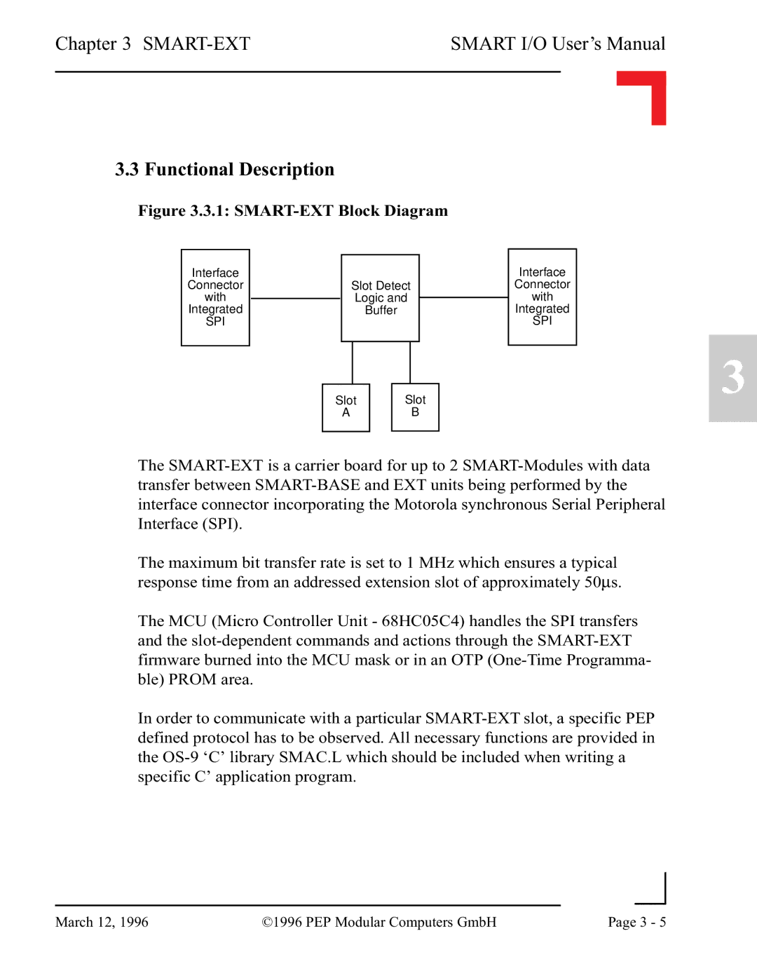
Figure 3.3.1: SMART-EXT Block Diagram

Interface


Interface


Connector


Slot Detect


Connector

with


Logic and


with


Integrated


Buffer


Integrated

SPI


SPI


Slot

Slot

A

B

The SMART-EXT is a carrier board for up to 2 SMART-Modules with data transfer between SMART-BASE and EXT units being performed by the interface connector incorporating the Motorola synchronous Serial Peripheral Interface (SPI).

The maximum bit transfer rate is set to 1 MHz which ensures a typical response time from an addressed extension slot of approximately 50μs.

The MCU (Micro Controller Unit - 68HC05C4) handles the SPI transfers and the slot-dependent commands and actions through the SMART-EXT firmware burned into the MCU mask or in an OTP (One-Time Programma- ble) PROM area.

In order to communicate with a particular SMART-EXT slot, a specific PEP defined protocol has to be observed. All necessary functions are provided in the OS-9 ‘C’ library SMAC.L which should be included when writing a specific C’ application program.

3


March 12, 1996

©1996 PEP Modular Computers GmbH

Page 3 - 5


Page 83
Image 83
Pepper Computer RS232, RS485 user manual SMART-EXT Block Diagram