Pepper Computer RS232, RS485 user manual SM-ADC1 Input Shematic Diagram

Models: RS485 RS232

1 320
Download 320 pages 36.43 Kb
Page 247
Image 247

Chapter 5 Analog Modules

SMART I/O User’s Manual


5.4.5 Functional Description

The SM-ADC1 has 6 differential voltage or current inputs depending on the ordered type. An on-board EEPROM contains board specific calibration data, module ID byte, sub ID byte and production data. A DC/DC converter generates the 5V to ±15V power requirements for the ADC converter and provides additional system isolation.

5.4.5.1 Input Circuitry

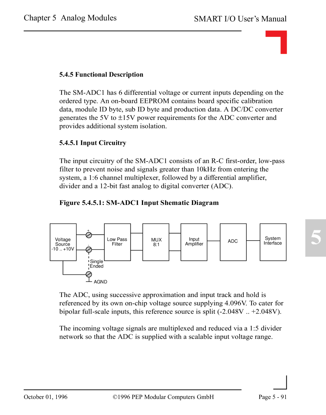
The input circuitry of the SM-ADC1 consists of an R-C first-order, low-pass filter to prevent noise and signals greater than 10kHz from entering the system, a 1:6 channel multiplexer, followed by a differential amplifier, divider and a 12-bit fast analog to digital converter (ADC).

Figure 5.4.5.1: SM-ADC1 Input Shematic Diagram

Voltage

Source

-10 .. +10V

+

Low Pass

-Filter

Single

Ended

AGND

MUX

8:1

Input

Amplifier

ADC

System

Interface

5

The ADC, using successive approximation and input track and hold is referenced by its own on-chip voltage source supplying 4.096V. To cater for bipolar full-scale inputs, this reference source is split (-2.048V .. +2.048V).

The incoming voltage signals are multiplexed and reduced via a 1:5 divider network so that the ADC is supplied with a scalable input voltage range.


October 01, 1996

©1996 PEP Modular Computers GmbH

Page 5 - 91


Page 247
Image 247
Pepper Computer RS232, RS485 user manual SM-ADC1 Input Shematic Diagram