Chapter 3 | SMART I/O User’s Manual | |||
|
|
|
|
|
|
|
|
|
|
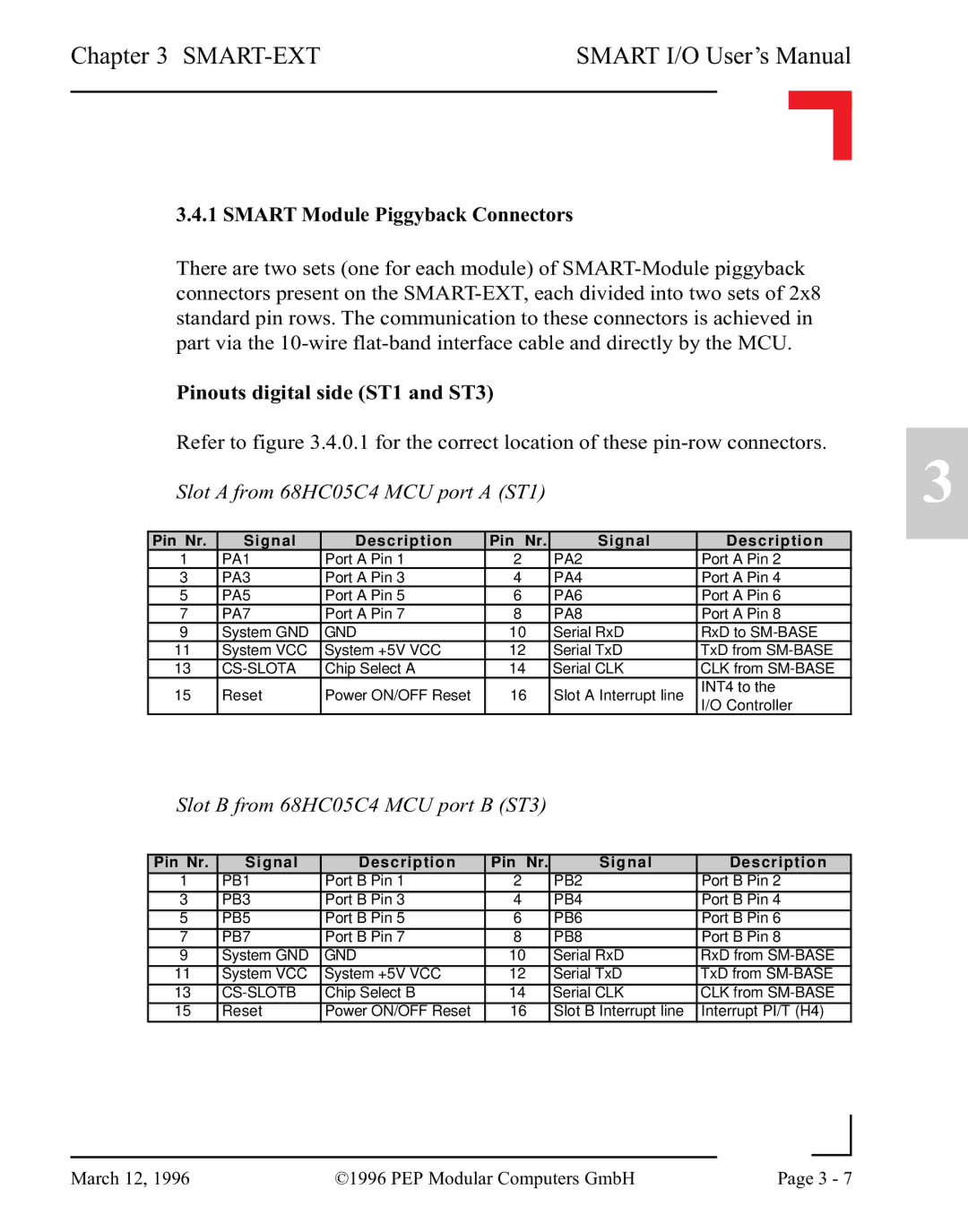
3.4.1 SMART Module Piggyback Connectors
There are two sets (one for each module) of
Pinouts digital side (ST1 and ST3)
Refer to figure 3.4.0.1 for the correct location of these
Pin Nr. | Signal | Description | Pin Nr. | Signal | Description | |
1 | PA1 | Port A Pin 1 | 2 | PA2 | Port A Pin 2 | |
3 | PA3 | Port A Pin 3 | 4 | PA4 | Port A Pin 4 | |
5 | PA5 | Port A Pin 5 | 6 | PA6 | Port A Pin 6 | |
7 | PA7 | Port A Pin 7 | 8 | PA8 | Port A Pin 8 | |
9 | System GND | GND | 10 | Serial RxD | RxD to | |
11 | System VCC | System +5V VCC | 12 | Serial TxD | TxD from | |
13 |
| Chip Select A | 14 | Serial CLK | CLK from | |
15 | Reset | Power ON/OFF Reset | 16 | Slot A Interrupt line | INT4 to the | |
I/O Controller | ||||||
|
|
|
|
|
Slot B from 68HC05C4 MCU port B (ST3)
Pin Nr. | Signal | Description | Pin Nr. | Signal | Description |
1 | PB1 | Port B Pin 1 | 2 | PB2 | Port B Pin 2 |
3 | PB3 | Port B Pin 3 | 4 | PB4 | Port B Pin 4 |
5 | PB5 | Port B Pin 5 | 6 | PB6 | Port B Pin 6 |
7 | PB7 | Port B Pin 7 | 8 | PB8 | Port B Pin 8 |
9 | System GND | GND | 10 | Serial RxD | RxD from |
11 | System VCC | System +5V VCC | 12 | Serial TxD | TxD from |
13 |
| Chip Select B | 14 | Serial CLK | CLK from |
15 | Reset | Power ON/OFF Reset | 16 | Slot B Interrupt line | Interrupt PI/T (H4) |
3
|
|
|
|
March 12, 1996 | ©1996 PEP Modular Computers GmbH | Page 3 - 7 | |
|
| ||