SMART I/O User’s Manual | Chapter 6 Communications Modules | |||
|
|
|
|
|
|
|
|
|
|
6.2.7 Register Description
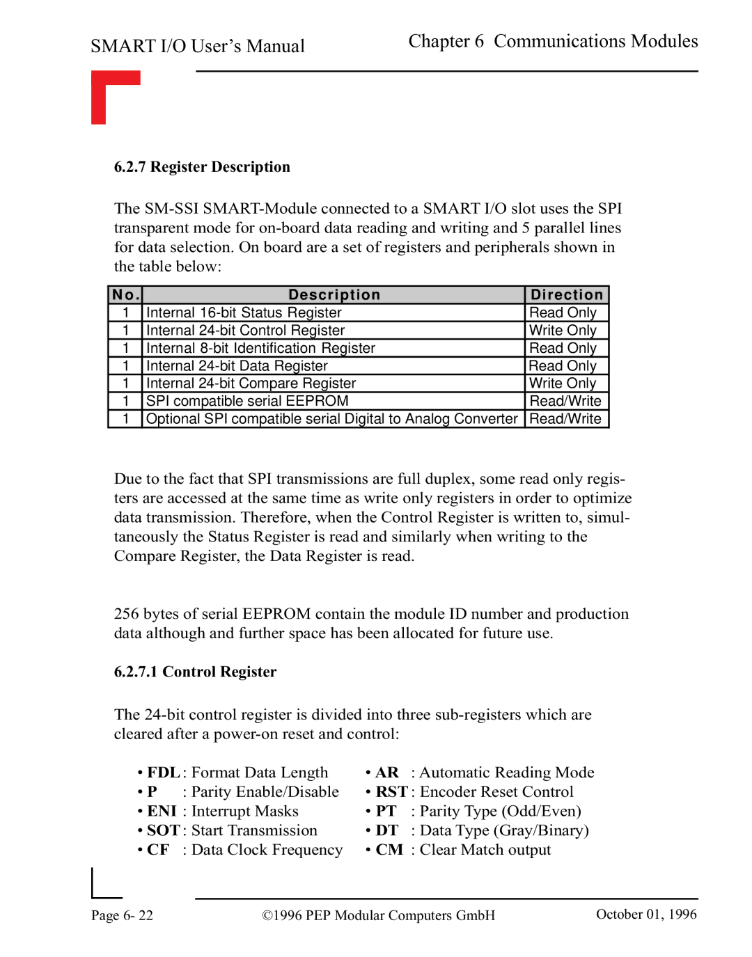
The
N o . | Description | Direction |
1 | Internal | Read Only |
1 | Internal | Write Only |
1 | Internal | Read Only |
1 | Internal | Read Only |
1 | Internal | Write Only |
1 | SPI compatible serial EEPROM | Read/Write |
1 | Optional SPI compatible serial Digital to Analog Converter | Read/Write |
Due to the fact that SPI transmissions are full duplex, some read only regis- ters are accessed at the same time as write only registers in order to optimize data transmission. Therefore, when the Control Register is written to, simul- taneously the Status Register is read and similarly when writing to the Compare Register, the Data Register is read.
256 bytes of serial EEPROM contain the module ID number and production data although and further space has been allocated for future use.
6.2.7.1 Control Register
The
• FDL: Format Data Length | • AR | : Automatic Reading Mode | |
• P | : Parity Enable/Disable | • RST : Encoder Reset Control | |
• ENI : Interrupt Masks | • PT | : Parity Type (Odd/Even) | |
• SOT: Start Transmission | • DT | : Data Type (Gray/Binary) | |
• CF | : Data Clock Frequency | • CM : Clear Match output | |
|
|
|
|
Page | 6- 22 | ©1996 PEP Modular Computers GmbH | October 01, 1996 |
|
|
|
