Chapter 5 Analog Modules | SMART I/O User’s Manual | |||
|
|
|
|
|
|
|
|
|
|
5.2.5 Functional Description
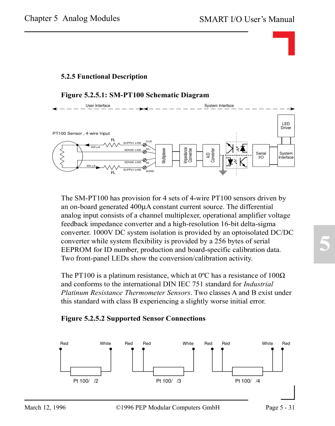
Figure 5.2.5.1: SM-PT100 Schematic Diagram
User Interface
PT100 Sensor ,
RL | CUR |
|
SUPPLY LINE |
| |
|
| |
400 μA | IN- | Multiplexer |
SENSE LINE | ||
SENSE LINE | IN+ |
|
|
|
400μA
SUPPLY LINE
System Interface
|
| Impedance Converter |
| A/D Converter |
|
|
| ||
|
|
| ||
|
|
|
|
|
Serial
I/O
LED
Driver
System
Interface
RL
AGND
The
The PT100 is a platinum resistance, which at 0ºC has a resistance of 100Ω and conforms to the international DIN IEC 751 standard for Industrial Platinum Resistance Thermometer Sensors. Two classes A and B exist under this standard with class B experiencing a slightly worse initial error.
Figure 5.2.5.2 Supported Sensor Connections
Red | White | Red | Red | White | Red | Red | White | Red |
Pt 100/ /2 | Pt 100/ /3 | Pt 100/ /4 |
5
|
|
|
|
March 12, 1996 | ©1996 PEP Modular Computers GmbH | Page 5 - 31 | |
|
| ||