Contents
Smart I/O User’s Manual
This page was intentionally left blank
Preface
Revision History
For your safety
Special Handling and Unpacking Instructions
Two Years Warranty
Preface
Chapter
SMART-EXT
Analog Modules
This page was intentionally left blank
Table of Contents
Smart I/O User’s Manual Introduction
General Information
Weights & Measures
Optional Bracket Mounting
Smart I/O User’s Manual Introduction
I t
Product Overview
O d u c t
Ordering Information
Esc r i p t io n
Product Information
B a SE Power Consumption Min
SCR2
Overview
Installation
Smart I/O User’s Manual Introduction
2.1 Smart I/O Module Installation
Smart I/O Module Installation
Screw Terminal Block Installation
3 RJ45 Telephone Connector Installation
5.1 Battery Piggyback Installation
Battery Installation
Before Installing
ISaGRAF-Installation
2.1 Typical Opening Screen
Installation of the ISaGRAF for Windows Workbench
Smart I/O User’s Manual Introduction
2.3 ISaGRAF Program Group
Installation of PEP Library Functions
3.1 illustrates the Installation Start-up screen
Introduction Smart I/O User’s Manual
3.2 Power Up Messages
Profibus
Demo Application
Introduction Smart I/O User’s Manual
This page has been left blank intentionally
SMART-BASE
Smart I/O User’s Manual SMART-BASE ISaGRAF Programming
SMART-BASE
D C
Specifications
Rear View
Board Overview
Front view
Functional Description
0.1 Smart I/O Block Diagram
Interrupt Logic
Jumper J1 Boot Selection Pin Connector
Configuration
Pinouts
Jumper J6 LED Function Pin Connector
SMART-Module location #0 ST5 pinouts
Smart Module Piggyback Connectors
Pinouts process side ST6, ST4 and ST2 for Modules #0 to #2
SMART-Module location #2 ST1 pinouts
Screw Terminal Pinouts
Timer I/O Screw Terminal SCR1
3.1 Timer I/O TIN Schematic
Supply Screw Terminals SCR2
3.2 Timer I/O Tout Schematic
Pin Nr Signal Description
5 RS232 Telephone Connector BU1
Pin Nr Signal
SPI Connector ST7
Software Requirements
‘C’ Programming
SMART-BASE Library
Hardware Requirements
Input
SMTselIn Syntax
Description
Example
Output
SMTsettout Syntax
SMTpre Syntax
Example for a Square Wave Generator
SMTstasto Syntax
Value
SMTrd Syntax
Input Pointer to a variable in which to place the read
SMTtin Syntax
SMTstat Syntax
Description of the Timer Status Register TSR
SMTout Syntax
SMLed Syntax
SMwdon Syntax
SMwdtrig Syntax
SMwdoff Syntax
ISaGRAF Board Parameters
ISaGRAF Programming
ISaGRAF Operate Calls
Voltage Time
RetVar = OPERATEiovar, OSTARTCOUNTER, null
Opreload
Examples
Flash Utility
Example to download ISA11 module and store in Flash
SMART-EXT
Smart I/O User’s Manual SMART-EXT
SMART-EXT
SPI
1 SMART-EXT Block Diagram
0.1 SMART-EXT Pinout Overview
CS-SLOTA
Pinouts digital side ST1 and ST3
Parallel I/O Screw Terminals Scra and Scrb
Pinouts process side ST2 and ST4
Pinouts for this 10-pin connector
SPI Connectors ST5 and BU1
This page has been left blank intentionally
Digital Modules
SM-DIN1
SM-REL1
This page was intentionally left blank
Introduction
Specifications
SM-DIN1
Front Panel Layout
Board Overview Component Side
Functional Description
5.1 SM-DIN1 Schematic Diagram
6.1 SM-DIN1 Configurable Filter
Configuration
Pinouts Screw Terminal Pinouts
Input Circuit
Connection
8 ‘C’ Programming 4.1.8.1 SM-DIN1 Library
SMDIN1Init Syntax
SMDIN1DeInit Syntax
SMDIN1Get Syntax
ISaGRAF Programming ISaGRAF Board Parameters
ISaGRAF Operate Calls
Smart I/O User’s Manual Digital Modules
OFF
SM-DOUT1
Yellow LEDs User Descriptor Fields
5.1 SM-DOUT1 Schematic Diagram
There are no jumpers to configure on the SM-DOUT1
Output Circuit
Digital Actuators
8 ‘C’ Programming 4.2.8.1 SM-DOUT1 Library
SMDOUT1Init Syntax
SMDOUT1DeInit Syntax
SMDOUT1Get Syntax
SMDOUT1Set Syntax
Module Specific Information
ISaGRAF Operate Calls
Digital Modules Smart I/O User’s Manual
This page has been left blank intentionally
SM-REL1
Yellow LEDs Green LED Yellow LED
5.1 SM-REL1 Schematic Diagram
Configuration Jumper J1 Eeprom Protection
Vccext
8 ‘C’ Programming 4.3.8.1 SM-REL1 Library
SMREL1Init Syntax
SMREL1DeInit Syntax
SMREL1Reset Syntax
SMREL1GetRly Syntax
SMREL1SetRly Syntax
SMREL1GetLed Syntax
SMREL1SetLed Syntax
SMREL1GetExtVcc Syntax
ISaGRAF Programming ISaGRAF Board Parameters
ISaGRAF Operate Calls
Oextpower
Oextpower
SM-ACI1
Specifications
Front Panel Layout
Board Overview
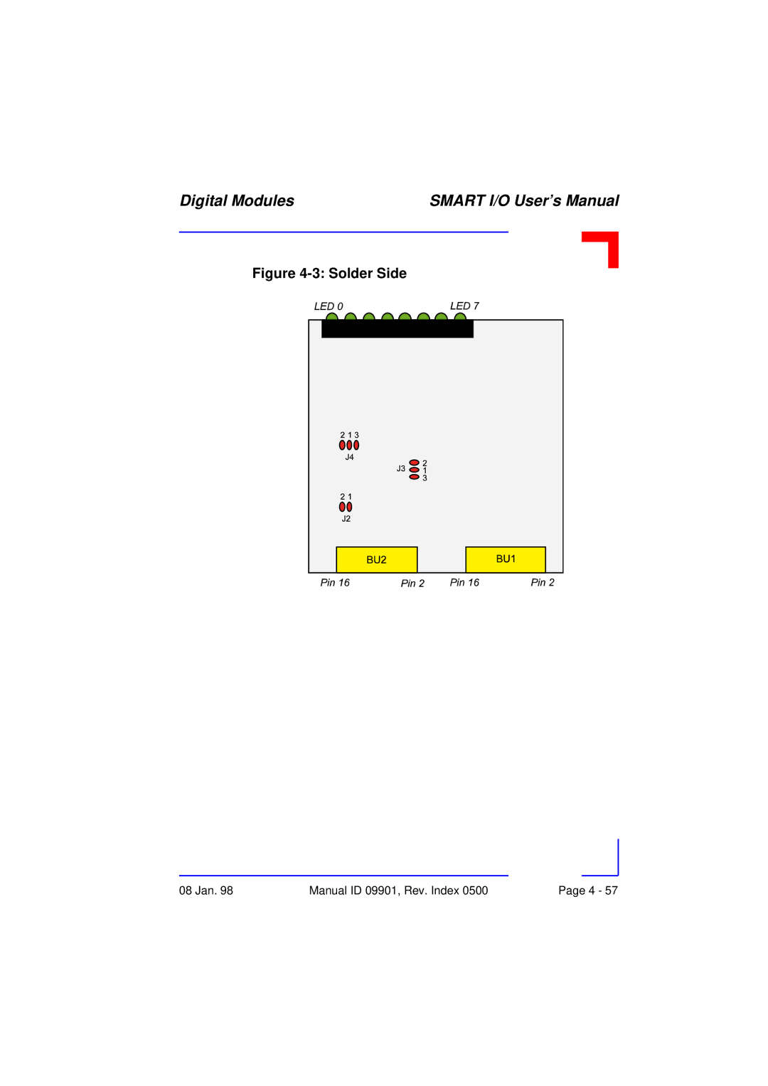
Solder Side
Functional Description
Configuration
SM-ACI1 Configurable Filter
Screw Terminal Pinouts
Pinout/Signal Relationship
Connection
Ansi ’C’ Programming 4.4.8.1 SM-ACI1 Library
SMACI1Init
SMACI1DeInit
SMACI1Get
ISaGRAF Programming ISaGRAF Board Parameters
ISaGRAF Operate Calls
Oinitcode
Smart I/O
Analog Modules
SM-THERM
SM-ADC1
SM-DAC1
This page has been left blank intentionally
SM-DAD1
Analog Modules
Red LEDs User Descriptor Fields
Component Side
Board Overview
Input Circuitry
5.1 SM-DAD1 Input Schematic Diagram
Output Circuitry
5.2 SM-DAD1 Output Schematic Diagram
Jumper J4 and J5 DAC Output
Jumpers J1 and J2
Jumper J3 Eeprom Protection
Agnd
Connection Circuit
Analog Actuators
VOUT0 Agnd
8 ‘C’ Programming 5.1.8.1 SM-DAD1 Library
SMDAD1Init Syntax
SMDAD1DeInit Syntax
RetVal = SMDAD1GetVRaw0, 2, 0x07FF
SMDAD1GetVRaw Syntax
RetVal = SMDAD1GetV0, 2, 0x07FF
SMDAD1GetV Syntax
RetVal = SMDAD1PutVRaw0, 1, 0x0FFF
SMDAD1PutVRaw Syntax
RetVal = SMDAD1PutV0, 1, 0x7FF
SMDAD1PutV Syntax
SMDAD1SetLed Syntax
SMDAD1ClrLed Syntax
ISaGRAF Programming ISaGRAF Board Parameters
ISaGRAF Operate Calls
Represents the analog return variable and can
Smart I/O User’s Manual Analog Modules
SM-PT100
Front Panel Layout Board Overview Component Side
5.1 SM-PT100 Schematic Diagram
5.2 Tolerances between Class a and Class B Sensors
Pin Nr. Signal Description
PT100PT100
8 ‘C’ Programming 5.2.8.1 SM-PT100 Library
Read RAW Data
Initialization
Other Functions
Read Temperature Values
Calibration
Deinitialization
END
SMADCInit Syntax
SMADCCalibrate Syntax
SMADCSetCyclicCalib Syntax
SMADCSetSensorType Syntax
SMADCGetSensorType Syntax
SMADCSetPrecision Syntax
SMADCGetPrecision Syntax
SMADCSetMode Syntax
SMADCGetMode Syntax
SMADCSetSignal Syntax
SMADCSetGain Syntax
SMADCGetGain
SMADCEnableRead Syntax
SMADCEnableConversion Syntax
SMADCReadRaw Syntax
SMADCReadConverted Syntax
SMADCDeinit Syntax
Calibperiod Typechx
ISaGRAF Operate Calls
Correct iovar is passed or non-zero if an
SM-THERM
SM-THERM
5.1 SM-THERM Schematic Diagram
† Cold Junction point PT100 connection
PT100
8 ‘C’ Programming 5.3.8.1 SM-THERM Library
To execute the example
D 1 L E D A t u s
8.1 SM-THERM Programming Flow Diagram
SMADCInit Syntax
SMADCCalibrate Syntax
Uint8 PortNr Uint16 secs
RetVal = SMADCSetSensorType0, 1, Btype
SMADCGetSensorType Syntax
SMADCSetPrecision Syntax
SMADCGetPrecision Syntax
SMADCSetMode Syntax
SMADCGetMode Syntax
SMADCSetSignal Syntax
SMADCSetGain Syntax
SMADCGetGain Syntax
SMADCEnableRead Syntax
SMADCEnableConversion Syntax
SMADCReadRaw Syntax
SMADCReadConverted Syntax
Number of the port to de-initialize
ISaGRAF Programming ISaGRAF Board Parameters
ISaGRAF Operate Calls
Represents the analog return variable and can
This page has been left blank intentionally
SM-ADC1
PEP Modular Computers GmbH October 01
5.1 SM-ADC1 Input Shematic Diagram
Pin Nr. Signal Description
Analog Sensors
8 ‘C’ Programming 5.4.8.1 SM-ADC1 Library
From 0 to
SMADC1Init Syntax
Input Port number of module to initialise
RetVal = SMADC1GetVRaw0, 2, 0x07FF
SMADC1GetVRaw Syntax
RetVal = SMADC1GetV0, 2, 0x07FF
SMADC1GetV Syntax
SMADC1SetLed Syntax
SMADC1ClrLed Syntax
SMADC1DeInit Syntax
ISaGRAF Programming ISaGRAF Board Parameters
ISaGRAF Operate Calls
Represents the analog return variable and can
Oenablelinecheck
Osetlinelimit
This page has been left blank intentionally
SM-DAC1
Current Sense Circuitary Converters
5.1 SM-DAC1 Output Shematic Diagram
OUT0
Current Output Circuit
Voltage Output Circuit
8 ‘C’ Programming 5.5.8.1 SM-DAC1 Library
SMDAC1Init Syntax
SMDAC1OpenLoop Syntax
SMADAC1Operate Syntax
SMDAC1StandBy Syntax
RetVal = SMDAC1PutVRaw0, 1, 0x0FFF
SMDAC1PutVRaw Syntax
RetVal = SMDAC1PutV0, 1, 0x0FFF
SMDAC1PutV Syntax
SMDAC1SetLed Syntax
SMDAC1ClrLed Syntax
SMDAC1DeInit Syntax
ISaGRAF Programming ISaGRAF Board Parameters
ISaGRAF Operate Calls
OALED1ON, OALED2ON
Ogetlinestate
Communications Modules For
Communications Modules
Communications Modules Smart I/O User’s Manual
This page has been left blank intentionally
SM-RS232
Communications Modules
Yellow LED Green LED
5.1 SM-RS232 Schematic Diagram
Jumper Settings Description
Interface
ISaGRAF Programming ISaGRAF Board Parameters
Communications Modules Smart I/O User’s Manual
ISaGRAF Operate Calls
Ret = OPERATEkeyboard, Oserialread
Return
$ xmode baud=19200 cs=7 par=none /scc3 return
Smart I/O User’s Manual Communications Modules
SM-SSI
Eeprom Prom
5.1 SM-SSI Schematic Diagram
SSI Operation
6.1 SM-SSI Timing Diagram
6.2 SM-SSI Timing Diagram for serial transfer
Control Register
Register Description
CTRL3 Register
CTRL1 Register
CTRL2 Register
ER1
Compare Register
Identification Register
Status Register
Data Register
STAT2 Register
Tested Sensors
Match Function
CLK+
SM-SSI
12 ‘C’ Programming 6.2.12.1 SM-SSI Library
SMSSIInit Syntax
SMSSIDeInit Syntax
SMSSISetSetPoint Syntax
SMSSISetCtrlReg Syntax
SMSSIGetStatus Syntax
SMSSIGetData Syntax
13.1.1 Function block of the SM-SSI Module Command
Setpoint Port Ctrx Error Position Statusx
This page has been left blank intentionally