Chapter 2 | SMART I/O User’s Manual | |||
|
|
|
|
|
|
|
|
|
|
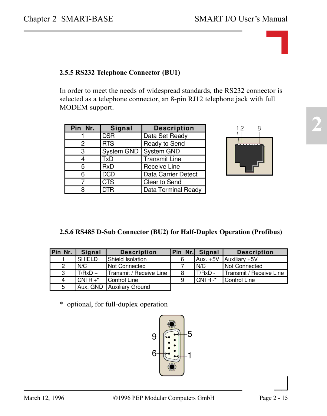
2.5.5 RS232 Telephone Connector (BU1)
In order to meet the needs of widespread standards, the RS232 connector is selected as a telephone connector, an
Pin Nr. | Signal | Description |
| 1 2 |
| 8 |
|
| |||||||
1 | DSR | Data Set Ready |
|
|
|
|
|
|
|
|
|
|
|
|
|
2 | RTS | Ready to Send |
|
|
|
|
|
|
|
|
|
|
|
| |
|
|
|
|
|
|
|
|
|
|
|
| ||||
3 | System GND | System GND |
|
|
|
|
|
|
|
|
|
|
|
| |
4 | TxD | Transmit Line |
|
|
|
|
|
|
|
|
|
|
|
| |
5 | RxD | Receive Line |
|
|
|
|
|
|
|
|
|
|
|
| |
6 | DCD | Data Carrier Detect |
|
|
|
|
|
|
|
|
|
|
|
| |
|
|
|
|
|
|
|
|
|
|
|
| ||||
7 | CTS | Clear to Send |
|
|
|
|
|
|
|
|
|
|
|
| |
8 | DTR | Data Terminal Ready |
|
|
|
|
|
|
|
|
|
|
|
| |
2.5.6 RS485
Pin Nr. | Signal | Description | Pin Nr. | Signal | Description |
1 | SHIELD | Shield Isolation | 6 | Aux. +5V | Auxiliary +5V |
2 | N/C | Not Connected | 7 | N/C | Not Connected |
3 | T/RxD + | Transmit / Receive Line | 8 | T/RxD - | Transmit / Receive Line |
4 | CNTR +* | Control Line | 9 | CNTR | Control Line |
5Aux. GND Auxiliary Ground
*optional, for
9![]()
![]()
![]()
![]() 5
5
6![]()
![]()
![]()
![]() 1
1
2
|
|
|
|
March 12, 1996 | ©1996 PEP Modular Computers GmbH | Page 2 - 15 | |
|
| ||